A possible solution to multiple variable length bed serving

I saw in the Q&A that having Farmbot serve multiple beds is almost impossible as is.

I am considering starting a farming business and find Farmbot a very interesting asset. But having to buy and maintain one per bed is a showstopper for many reasons, not just financial or practical.

What about offering the following?
A Farmbot that would be coupled to a 4 bike wheel cart with a small electric engine to move the cart. The cart could easily serve multiple beds. The bot could operate the cart’s engine the same way it does on the gantry.

To keep the cart above the bed, some simple furrows could serve as guidelines. Water supply and power could come from above as is often the case in greenhouses. Water coonection could use standard connections to make it easy to disconnect from one bed and connect to the next.

You could give the cart specs leaving every Farmbot user the responsibility to make it or have it built at his end and maybe have an open source collective development of the cart.

This would offer many advantages :

  • no limits to the length of each bed
  • no need to install tracks
  • no need for you to source, store, pack and ship track railings
  • serving multiple beds easily
  • better Farmbot amortization
2 Likes

First, mine is a non-expert answer, but my guess is the problem with removing the tracks is loss of accuracy.

The reason that this project can be as “simple” as it is is the rails provide accuracy in all three axis which leads to easy repeatability of motion.

Your solution seems simple, but isn’t because the furrows are of an unknown and changeable depth (Z-axis), they can’t provide a precision side to side accuracy (Y-axis) and there is no hard start to provide a repeatable starting point (X axis). To solve this you would have to add in some other none mechanical system that can provide that accuracy. That isn’t impossible, and could be done with differential GPS with some inertial correction system or some kind of on-site accurate location system like LED beacons that could be triangulated with cameras or something.

Without the accuracy, you would need to do all the tasks based on visual identification. i.e. That is a weed, so I will kill it, that is a plant so i will water it, that is a thirsty plant so i will water it more, etc.

Again non-official answer.

I think we’re overthinking the problem. I’ve seen the issue for serving multiple beds pop up in numerous threads.

You want to keep the bot’s current accuracy, so you don’t want to mess with its current dimensions too much.

I have a simple solution. Place the entire bot on another rails.

Imagine the standard FarmBot Genesis, 3.0m * 1.5m. Let’s say the Y axis is the longer axis (3m) and the X axis is the short one.

Now instead of mounting this bot on a 3.0 * 1.5 bed, you mount it on a set of rails in the Y direction. Then you can place beds of equal dimensions next to each other (their long sides touching). So now the bot can move internally within the XYZ space, but the entire bot can shift on the X axis towards the left and right.

The bot won’t lose its rigidity because we didn’t make it any bigger than it is now. It might lose some stability but we can tackle that by making the outer rails (the one that carries the whole bot) snap into place or lock it down with some pins or brakes.

1 Like

I’m not really sure I understand your answer. Are you suggesting that the pair of rails that support the gantry slide sideways on a set of rails? If so I think that would be very hard.

I’ve been thinking more about the solution to your problem and I think it is cheaper rails.

I think the minimum rail setup for a SPIN farming type setup would be 2x4s. What I was thinking was to create a prepared bed and then hammer in treated 2x4 posts every 4’ on either side and then cut them all to the same level to allow them to be capped with a horizontal 2x4s which would form the rails. Due to the imperfect surface of the 2x4s you would upgrade the present guide wheel design to one that uses something larger like skateboard or rollerblading wheels. That whole system could be moved around off-rail on outboard bicycle wheels that extended below the smaller wheels when off rail, much as you describe, but uses the rails for accurate positioning when farming.

All you’d have to add in is a system that would accurately and repeatably zero the X-axis at the start of the rails and a system to replace the feed belt as you describe in a greenhouse or make the gantry system untethered.

I entered a different post about a powered trailer that could feed and follow the gantry without needing the gantry’s positioning accuracy, which you’d need in a SPIN setting. I’m guessing that the internet link for programming the system could be a one time affair through a cell phone tether.

My question is whether accurate post positioning is possible to create an accurate rail system on top of. Then also whether it would be better to create the rails with a pair of 2x4s in a T arrangement to prevent sag or warp between posts. You might even cover the top 2x4 with aluminum flashing to smooth the surface and lower moisture cycling in the wood. In any case you’d still need to attach a line of toothed belt for accurate X-positioning.

This system would not solve watering issues but if cycled around enough could perform complicated planting patterns, weeding, moisture testing and could be smart enough to program in plant succession patterns.

The question I have is how much accuracy is required. This will decide if this is a sane idea or not. Yes RichardJHauser is right you can lose accuracy.

A general ultrasonic sensor you can get is HC-SR04 it does 2 cm to 400 cm with a 3 mm+ or - error rate and more expensive versions(about 100 USD each) the same sensor type does 2 cm to 700 cm with same error rate. If this was suitable error you would place one on each leg of the gantry. Lidar units that are more expensive again can end up doing 1.5mm+ or - over 40meters. So changing Y from rails to wheels could massively extend operational size.

there is no hard start to provide a repeatable starting point (X axis).

Exactly how exact does the starting point need to be is 6mm or 3mm variation close enough. 6mm to 3mm would be absolutely fail for 3d printing or cnc work but this is not 3d printing or cnc work this is planting and caring for plants.

The best differential gps out there is https://www.swiftnav.com/piksi.html yes this would add 1000 dollars to build cost. Its exact to ±1 cm in all directions for a 200 meter circle around the fixed location transmitter and you can add more beacons to expand your covered area. Not that I would exactly want to make my home garden dependant on gps but some people do have big gardens.

Lidar and ultrasonics will allow you more exact than GPS. differential GPS would get you close enough to find your lidar or ultrasonics reflection targets.

permanemar idea of no tracks most likely is a mistake. Issue with simple furrows is they deform due to compaction and other things. Basically machine on wheels has weight and earth will deform unevenly it unless something is spreading the load evenly by either movement or track. I don’t see that a farmbot movements are going to be 100 percent evenly spread. Using ultrasonic you would still most likely put down open tracks Angle aluminium that the cart drives into as a load spreader. Why to give a constant predictable height and resist wearing unevenly. Also between beds if a open track can be used you can have a flat surface for the wheels to drive on so it can drive between beds crossing over human walkways.

Please note for me I would not be depending of a machine like farmbot for watering. I use wicking garden bed designs that to start off with are highly water effective more effective than above watering and naturally suite most plants. Most likely thing in water I would want a farmbot doing is spraying like bicarb soda for fungus control or other foliage fertilisers so this will make my life simpler as in a lot of cases with spray items those could be placed on board in tanks.

RichardJHauser I lived on a properly for quite some time I can tell you depending on soil type hammering poles onto ground might be the biggest mistake you have ever made. Yes at start everything for the tracks might be nice as square but then mother nature kicks in and each hammered in post can end up attempting to tilt in a different direction. So some ways cart on wheels with track on ground may be the best option. Cart on ground can be design to avoid becoming nasty jammed by deformation. Placing the rails at ground level on top of two fairly strong boards does resist deformation quite a bit.

Yes even with lidar and ultrasonic targets those would need to be corrected from time to time due to what nature has done. One of my biggest worries with current farmbot design is how it going to handle earth movement. Scary enough were I am between some of the soils between dry and wet in can be over 4 inchs of movement if that happened to be outside of bed outside so attempting to make gantry 8 inchs wider I don’t see how current design would stay functional it would have basically broken like a wish bone. That is something else that has to be considered even with a wheel cart design how much stuff is going to move.

Yes, that is what I am suggesting. I think if you mount the whole FarmBot on top of a rigid frame rather than directly to the bed, you have the option to slide this frame sideways.

I think on the sideways rails, you could have holes in the rails where a pin can snap into to lock the frame into place. Then you also have a guaranteed new “home” position for that particular bed.

Witness my awesome MS Paint skillzz… :smirk:

This is supposed to represent the sideways-rails, seen from the side. The frame of the FarmBot would be mounted on wheels similarly to how the gantry system is currently mounted on its own rails.

The red pin represents wheels which are in free mode. The whole frame can slide left and right and FarmBot won’t know its home position. This is the case when you are switching between beds.

The green pin represents the situation when the frame is locked to a particular bed. The system will know when it’s locked to a bed and which bed this is. Also, because you make sure these notches are always at the beginning of a bed, FarmBot now knows this bed’s home position.

The pin could be raised by magnets, screwing or spring-loaded or a combination thereof.

“The question I have is how much accuracy is required.“ I agree and think the accuracy needed depends on tasks required. I think the task that needs the most accuracy is sowing seeds and then weeding, assuming that needs to visually see a spot of green and decide with limited intelligence if that is a weed or a plant based on relative location to a planted seed. My guess is that would need about 2cm of accuracy as that is about how close you could weed to a plant, though this is a guess as I don’t have any understanding of computer vision to discern a weed from a spreading plant root or a drooping leaf, etc.

As for the idea of a completely untethered bot is a fine idea, and thank you for the link to the accurate GPS, but I think it is outside the scope of this project. That is not to say that it isn’t interesting, especially to me, but out of place here. I think the goal of this project is mass market the ideas and drop the price down so that everyone can have one running in their back yard or in small greenhouses.

I think a mass market project like this will lay the ground work for the systems necessary to create future self-guided systems. I’d love to see something that could free range around a large area, but the problems would be massive even once the issues of accurate location are solved. i.e. larger rolling resistance, higher power requirements, need for batteries, need for solution for recharging batteries, uneven ground, complicated movement programming, etc. Where as, rails give simple solutions to all of them.

I am working on a drive base prototype. I do think this is possible. With the right sensors. Also using mapping of the ground. Some what like the auto leveling on 3d printer beds but with lidar. The base unit may need its own computer. But with ROS and pi i think it is possible. There are other platforms as well. Ardupilot for example. It may be where the base is just sending telemetry back to a main server that does the bulk of the heavy processing. I am actively working on a small scale base to test this on. It may turn out to be a total flop but it should be fun to try.

I wonder if fixed accuracy is a limitation for the larger garden affordability? It does reduce the cost of the small garden, but potentially limits the larger one.

It limits the design of the Farmbot, and the size. At some point perhaps we are going to want to include a locate pod, to fix the location of the bot and pass this info on to the the control. This could serve a number of bots!

A lazer plane level and a response lazer from the bot would give hight and angle to provide a unique location prior to performing the job.

Of course lasers can damage the eye of the appreciative audience! But another solution or a protection scheme can be developed!

Main reason I was asking about accuracy was not just about building a untethered bot but also reducing complexity of tethered to allow larger areas to be used. .

Now my brain just caught up with itself. No wonder the length is limited to about 3 meters the longest axis is done wrong. Using a looped belt equals putting force in 6 meters of belt for a 3 meter bed.
http://www.makerstore.com.au/blog/v-slot-the-ox-cnc-machine-and-the-everman-belt-drive-system/

The best in CNC belt drive is everman but the patent on that expires 2028-2029. Even so don’t stick belt in slot(so not covered by everman patent) and copy the on gantry drive of an ever-man would take max drive range from 3 meters to 6 meters using the same length belt.

There has been something feeling super odd about the farmbot every time I look at it. The odd thing is all large CNC with gantry all the drive motors are on/in the gantry and farmbot not all drive motors are on gantry.

A looped belt in the top of gantry makes sense to reduce number of moving wires. From what I see is the controller is on the gantry anyhow so this means wires are having to leave to drive the motors. Dependable CNC machine keeps the number of bending wires to a min.

If required accuracy is about 2cm remember Lidar for range measuring gives 3mm and ultrasonics give about 6mm having a belt in rail may not be required for the longest rail if drive is placed in gantry and it is using a track like a rail track

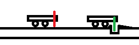
Using the cheapest ultrasonics a bed of over 7 meters would be possible. Yes you would stand up reflector plates at each end as end stops. Yes this is still a rail system. The thing to remember the longest axis is the most likely to have belt issues. So if the longest axis can be made belt less dependability will increase.

No belt into the longest axis would make it possible to pickup gantry and move it between rails. Since you have a camera all ready you could place some ID marker at end of a bed for gantry to work out where it is.

There are a few differences with me.

  1. I will not need something like farmbot to water plants.
    http://www.sgaonline.org.au/wicking-beds/
    I use wicking-beds. So you fill a under bed reservoir with water and that water travels up through the soil. The water level in the reservoir can be done with a basic float valve. This is a fairly natural automatic controlled watering system. If the float valve blocks up you have over a week to find out about it without the crops knowing anything.
  2. depend on how the seeder ends up designed over time I might not be needing the vacuum line either.

Something to remember if weather is going to be wet that would be the ideal time to-do maintenance on the gantry if you can bring the gantry inside.

http://www.urbanfoodgarden.org/main/vegetable-patch-design/vegetable-patch-design--size.htm

Part of my problem is the size of the machine. 2x3 meters is what people can take care of without investing in a machine if they are serous. Could people have garden beds double/treble this to meet food wants the answer is yes.

Please note you do not want wide than 2 meters as all this triggers is people walking on bed to get things. 1.4 meters wide 6 meters long would be head in the direction of right size. This is why at a min we need to serous-ally look at the longest rail and see what can be done. lidar sensors would let 75 meter beds for 400 dollars of sensors and possible 100 dollars of control system. Powering a bed that long would be a challenge.

What if the rails were also a rack. Using a pinion drive on to a rack. I like pvc. Its cheap. It is machinable. So using pvc pipe as a rail one could easily cut holes for a pinion gear to drive on. And it can also bear the weight of the gantry. Now mount the solar panel and batteries to the gantry. No more cable tracks other then the x and z axis. Unlimited in length. Easy to move. If water is not needed. This would work. The drive motors for the Y will need to be stronger. Nema 17 will not cut it.

2 m x 3 m. Your family garden is 9m x 18m and it is to small. If we have a wet spring we only get 1/2 the production that will only last tell March. We need greens into July before the garden produces. We also have a large community garden that is 4 times the size of our garden. We have it for the refugees that our community is helping but it is available for anyone in need. My wife is talking about doing more for the elderly as well. I would love to go bigger. I see this as the way to get there. I want something that is portable. Thats why I am looking at a drive base. Also if it can cover the same area as a large rail system it should be comparable in price. Very little is known about the actual run time of the bot. My best guess the farmbot Genesis runs once a day. Maybe twice. Depending on if it performs a weeding routine. the speed of the tasks will determine the size it can service. Be it a rail or a drive base. Also available power. Solar or grid.

I wonder if fixed accuracy is a limitation for the larger garden affordability? It does reduce the cost of the small garden, but potentially limits the larger one.
I am serous-ally not sure of that. I current think some of the farmbot selections without in fact improving accuracy limited it size. Like moving the longest axis belt drive motor off rail and on to gantry could allow the machines length to double and only add extra bits of rail wheels to achieve it. So move a max bed size from 3x1.4 meters to a 6x1.4 meters. T

Its a 1000 dollars to use GPS to give exact to 1 cm covering 200 meter circle.

http://www.digikey.com.au/en/supplier-centers/d/decawave
Using non GPS radio beacons like decawave gives inside 10cm using 100 to 200 meter range beacons outside. Please remember human driving is normally not ± 10cm. Beacons can service any number of bots. So the stuff to cover quite a large area is not exactly cheap but its not insanely expensive either. If you are inside 10cm of where you want to be camera to tag or lidar or ultrasonics can be used from fixed points after that.

The bigger question always is will the machine pay for itself. Fixed accuracy is not a major battle there are means to achieve that. You start out with basically lossy accuracy to get you to calibration points then use beacons and targets simple enough to get inside a cm to 2. How to power the machine and items like that are the bigger problem that get in ways of going to larger and larger sizes.

Of course if the system can operate more lossy lower the complexity you need to perform in calibration. Lower exactness required lower the price of the overall machine.

The 2m x 3m is too small for where I am as well. 2m x 3m is what is classed that people with full time jobs can take care of successfully by manual means. Basically I class 2m x 3m as the bare min the farmbot has to out do. 2m x 6m is in fact just workable in a good season where I am. I know this from using wheel barrow garden beds. I live in subtropical so I have no winter or rainy season to worry about so can grow all year round.

Bigger issue where I am is we do get watering restrictions. Another reason why I use wicking bed systems. Hand watering with hose can in fact refill wicking garden design. Where an automated watering system like farmbot would be against rules and not usable. Yes when they say hand watering they mean exactly that here all automated systems of watering for-bin unless running from own tank. Of course dry can equal tanks running low as well. The fact that water line to farmbot would have to be disabled at times I don’t see major advantages to it so I drop that out of my consideration as a major feature.

Few things to consider.

  1. Solar panel on gantry will increase its shadow on crops this may be more of a hindrance than wanted. Yes working out what is the largest that can be operated with power cables has valid reasons to research.
  2. PVC is easy to machine because its not in fact that hard so under load it could wear quite badly.
  3. mass of complete device. This is something to always keep in mind soil compaction under where device repeat runs long one of the reason why I am not recommending losing tracks of some form.

The reason why I was looking to range sensors is to be able to use drive wheels on normal metal angle material still able to lay tracks to spread mass of machine on ground.

The run-time of bot is a very key question. Speed to complete all tasks would be heavily effected by how many tools it can carry on gantry so how many trip it has todo to get tools.

“Main reason I was asking about accuracy was not just about building a untethered bot but also reducing complexity of tethered to allow larger areas to be used.” I couldn’t agree more.

“Now my brain just caught up with itself. No wonder the length is limited to about 3 meters the longest axis is done wrong. Using a looped belt equals putting force in 6 meters of belt for a 3 meter bed.http://www.makerstore.com.au/blog/v-slot-the-ox-cnc-machine-and-the-everman-belt-drive-system/1” You lost me there, as the system as designed is not looped, but like the Everman without the lower belt and with the gear moved to the top of the gantry. https://farmbot-genesis.readme.io/docs/gantry

“There has been something feeling super odd about the farmbot every time I look at it. The odd thing is all large CNC with gantry all the drive motors are on/in the gantry and farmbot not all drive motors are on gantry.” You lost me again as all the drive motors on the Farmbot are on the gantry. Infact all are at the top of the gantry.

“Using the cheapest ultrasonics a bed of over 7 meters would be possible.” Maybe. My question for using ultrasonics is the need for a tight cone for measuring. i.e. How wide is the target area at 7m? But in any case if you go to the expense of replacing measured mechanical movement with a sensory feedback loop then 7m is not enough. I would say one of the major uses of this system would be for SPIN farming and then the standard bed length is 25’. The other standard use would be for greenhouses which commonly go to 96’. So I think you’d have to switch to a laser, but as I’ll show there is a simpler method.

“No belt into the longest axis would make it possible to pickup gantry and move it between rails.” I agree with the idea to make the gantry mobile between rails, but my idea is simpler and cheaper. Replace the V-slot rails with pairs of 2x4s screwed together in the shape of a T. Then wrap the top 2x4s with 8” wide aluminum flashing. This creates smooth rails for about $3/ft or ~$300 for a 96’ greenhouse down from $10/ft for the V-slot… You still need a solid traction system down the rails that will survive the elements, so I would glue a drive belt underneath the T on the outside of each side. The drive system would be twin traction drives like a tank with an identical belt which meshes with the belts on the rails. (like the Everman drive but the drive belt is looped.) The existing roller wheels would have to be replaced with something like skateboard or rollerblade wheels. Since the drive system can have slippage, we need to add in optical or mechanical flags at intervals down the rails to allow the system to first zero and then error correct during movement. You could also just take one of the optical encoders and have it run off its own cog wheel. In this way if the drive system slipped, the optical encoders would record the lack of motion and signal the system to correct.

Now all you need to add is a system that replaces the cable carrier and for that I suggest a powered trailer. The supply trailer does not need exact positioning, just a system that would keep it within supply range of the gantry, so at bare minimum, take a deep cycle battery, a small electric motor and some relays and you could create a trailer that would dutifully stay with 1 meter behind the gantry. Add in a solar panel and any other feed supplies necessary like seeds, alternate tool heads, etc. and you have a system that could extend the X-axis of the Farmbot nearly indefinitely.

I’d love to see a rail that was a rack, but I haven’t found anything. I was thinking also of a plastic tape/chain designed with regular holes for solid drive, but I haven’t found it. The idea of modifying PVC is interesting, but I think it would be very hard in practice to create. Yes it is easy to drill a hole, but what you need is a hole regularly at every inch/cm, so dozens of holes per section.

The rest I answered in my response to OIAOHM, but I think we are on the same track.

RichardJHauser in one of the PDF I read one of the older designs had looped belt. Think it was the 0.4 was loop and I missed that it was fixed after that. So opps. Still the one thing from everman you want to keep belt stretching distances to a min where possible so I was not looking for motors up at the top of the gantry. So the design is still odd just not as odd as the early revisions were. Ultrasonics don’t stretch have predictable error zones.

How wide is the target area at 7m that is exploiting a trick if you have a sensor pointing off both directions gantry you only need functional measurement in 1 direction with overlap in middle. So a 4 meter sensor does 3.5 meters each way allow for a full 1 meter overlap in the middle. So distance to target on 7 meter bed for cheapest Ultrasonic is max of 4 meters. So 25 foot that is 7.62meters could be done by cheapest sensors with just reflectors at each end but you would be cutting your overlap zone down to bare bones. But I will cover another method.

http://www.maxbotix.com/documents/HRXL-MaxSonar-WR_Datasheet.pdf This was just a doc I could find quickly. It is one of the more expensive sensors for the 4 sensors 10meter range outdoor rated it would add about 600 USD with a spare and controller. But the issues with ultrasonics are fairly constant between makes and models.
Well constructed outdoor ultrasonics with exact to ±1 mm except for first 30cm that is ±5mm(echo issue) and 3-10 meter range only has a 11 inch target. Shorter the range ultrasonic smaller the target becomes. Well made is using the sound equal to a laser to the beem does not spread extremely. The first 30cm of error could be handled by the camera using a calibration stick.

Here is the thing most don’t consider. 96 feet or 30 meters beds yes they are fairly standard. If using the cheapest Ultrasonic range finder sensor and we have 2cm error to play with. There then becomes no need to point the ultrasonics straight down the track so now you can stand the reflectors next to track at about 3 meter spacings with some optical tag that the camera can read or mechanical tag to work out how far long it is. Yes optical tag would avoid having extra hardware on gantry. The non straight angle on the ultrasonic would add a mm or two of distance error but its an error that as long as the reflectors don’t move would remain 100 percent constant. Yes this is the same 4 sensors to the gantry as to-do 7 meters todo unlimited length. Yes a 25 foot 7.62meters bed could be done by using 6 reflectors instead of 4. More expensive sensor used less reflectors required but has a larger interference range as well so there can be a lot of cases were the cheaper ultrasonic sensors will be the best. Issue comes will having reflectors get in ways of cables and other things. 96 foot bed with 10 meter ultrasonics you would put in 8 reflectors 4 down each side 11inch squares normally you would paint a number on them or something. Thing with using ultrasonics you aim for overlap and avoid using min or max if after faily though

Now if the 5mm error due to echoing in ultrasonics is not a issue you could get away with 1 inch round reflectors put in at each meter and don’t go for expensive ranged sensor. That the thing with ultrasonics there is a lot of options if allowable error is large enough. Major advantage of ultrasonics not effected by the sun like lidar can be. In fact using the sensors on both sides of the gantry you can remove the 5 mm error. 5 mm error happens in first 30 cm so you can work around it.
1 meter peg spacing presuming 10 cm wide gantry.
peg-20cm-gantry-70cm-peg. Notice what has happened here. At the point were sensor on one side become not dependable the sensor on the other side is perfect. So ±2mm with correctly set-up ultrasonics in drive past configuration is possible. ±2mm is too big for high grade 3d printing for crop control is most likely over kill.

Rack and pinion on most CNC machines have the Rack up the top and the pinion under it.
The drive system would be twin traction drives like a tank with an identical belt which meshes with the belts on the rails.
Not a good idea you forgot this is a garden at times garbage will fall into near ground tracks. So you cannot put a exposed toothed track facing up without having trouble at some point or another.

With ultrasonics have a track to run in so you have one cross bed distance locked and distance to reflectors is locked. Yes as long as reflectors stay in fix position to track every thing is good.

Another part fun about ultrasonics most cases they don’t care if reflector is painted or not. 1-9 meter bed section markers for humans could be the reflectors.

Since the drive system can have slippage
That the thing slippage only counts if it not corrected for and if it larger than the allowable margin for error. Ultrasonics and reflectors slippage can be detected as long as reflectors placement is somewhere near right and it calibrated. This is a on going calibration this is not zero points hoping it remains calibrated.

Going to high grade ultrasonics will not bring cost down that much up to 96foot/30meter beds but will make cleaning of the lowest track simple. Take gantry off track hose/brush down track put gantry back. Everything on the gantry can be protected by housings the track long tracks are something that are not as protect-able. Lower grade waterproof ultrasonics out to 4 meters range could under 100 dollars of cost for 4 sensors. So the price of one 10 meter sensor will buy 4 shorter range ones with a bit if pvc pipe/3d printing to narrow beam. This is why I was asking so much about how accuracy is required because it makes a huge difference in cost on what sensors you can get away with. Of course some people would not want a peg every 1 to 3 meters. Range and housing equals cost in sensors. Ultrasonics have particular advantages over light based particularly outdoors at the price of max range.

Oh! Here is something interesting, it’s even on topic! Lol
I have a voltmeter/ammeter/amp hour/watt meter on my electric scooter. I got it from China on eBay for $34 . It senses the voltage and amperage going into the controller, and wirelessly sends the info to the display on the front of the bike, which displays all the information that can be calculated from that info!
There are only two power wires to the display, and two power and 2 sensor wires to the sensor.

We could reduce our wires to the Farmbot to 2 with something like this, simplifying and reducing cost! It sure simplified and reduced the cost of putting a meter on my scooter!

Link to the meter on eBay.com
http://www.ebay.com/itm/New-Multifunction-Wireless-DC-Voltmeter-Ammeter-Power-Meter-0-120V-100A-Shunt-/311347135201?hash=item487dbc42e1:g:6PsAAOSwBahVPOii

I found this picture and thought of this thread. LINK

Why does it have to be notched rails?

Part of this is stepper motor positioning.

What about instead you created a rails out of 2x4’s.

You scalp the edges at 45 degrees, and use a pair of wheels against these edges. This keeps the truck centered over the 2x4.

This leaves a flat bit. on top. For this, print what amounts to a continuous bar code. You print it on 8.5 x 11 averery weatherproof labels cut in strips and stick to the top of the beam. Now, instead of counting stepper pulses / counting notches, you use an optical scanner to read tick marks, and bar codes.

Possible problems. Bird crap, rain splash may obscure a section of tape. Put tapes on both rails. If one is unreadable, the machine assumes that that side is keeping up. But also a fault comes up to clean the rail.

Print barcodes every 3 inches so that the rack only has to move 3 inches to get reoriented.

1 Like