When installing the motors, at one point the the doc’s it suggests M3 x 16 mm screws and then later says M3 x 10 mm. In actuality, you need to go to the store and get yourself some M3 x 12 mm screws for the job. On at least one of the motors the 10 mm was to short (not enough threads in the end of the motor due to excessive chamfer.) I tried 16 mm but they are to long, so please change the to 12 mm and revised the doc’s to be consistent.
Missing instructions for installing the electronics boxes. Doesn’t seem like any way to mount the power supply inside of the 'black box" – I’m assuming it goes in there.
None of the cables are actually labeled with anything. This needs to be corrected.
Excessive use of abbreviations (like CC) with no definition of meaning.
The wires on the 12 conductor cable should have “numbers” on them. They are fairly readable on the end with connectors but on the ‘stripped’ end they can’t be read. You have to ohm out the cable to make sense of it.
For all the cable trays the docs carefully tell you to check the layout to make sure you have it correct because it can only go in one way. Well, there’s not a single image of what they should look like or where those ends should go. Took me at least 30 min’s on each to sort of figure out what “must be” the way. That’s lame. Take a photo and add it to the manual.
You should just include instructions for installing the second RAMPs wire. You put the wire in the kit and vaguely say, its in case you want a high powered output, but don’t describe how to hook the wire up. Standard should be to hook it up and you should give instructions for doing so.
Placement of the “CC” guides. You say, evenly space them. Why not just say where they should be. For the horizontal gantry guides, it seems you need one on each end, and evenly spaced across for the rest. I waisted a lot of time trying to calculate out where to place them – I know that’s my problem but do you really want every customer to figure that out and spend that time on it?
No information is given about how much clearance you need around your plot to accommodate the farmbot, (like you need at least x cm of clearance on each side) – like that. So you don’t know exactly where to build you plot till your done.
No specification for how much power is needed (AC power)
No temp specs for the product. BTW, given the parts being used, its a room temperature product. My greenhouse doesn’t get to cold, but it does get hot so I’m a bit concerned.
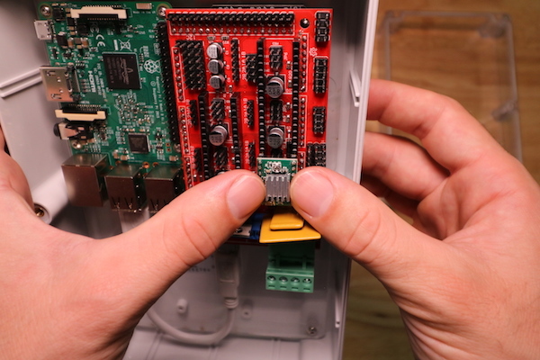
The X2 stepper motor connection is shown in the RAMPS wiring diagram. The motor wires can be plugged in either direction, which allows the user to choose the positive and negative directions of the motor.
Thanks for the quick turn around on the questions.
I think you should use M3 x 12 mm on the motors. At least one of my motors had a “deep” chamfer on the face and the screw only had two turns to bottoming out. Normally for fine threads, you want at least 3 ½ turns for full engagement. Just my opinion. Feel free to ignore.
What happens if I get X1 and X2 in the ‘wrong’ direction? Will they fight? Might that cause an error?
Yes, if X1 and X2 aren’t plugged in opposite each other, the motors will fight each other and the gantry will not move. The second x-axis encoder isn’t implemented in the software at this time.
Soil can be added up to the brim of the raised bed after installing the toolbays, but having the soil level slightly below the bed brim is fine.
You should suggest marking each end of one of the hoses and the z-axis motor/encoder pairs so that after you’ve run them through all the trays are you’re reading to hook up the other end you can tell the air vs water hose and you can tell the difference between the y-axis motor/encoder pair and the z-axis pair.
Documentation is everytime a hard step to get all the correct information. Farmbot.io provided the V1.2 docs with some updates that helped us a lot.
You can also check our documentation on our website at www.wefarmbot.com and our wiki: http://wiki.wefarmbot.com/doku.php
We tried to make it as clear as possible to help people during the set up.
Hope it can help you.
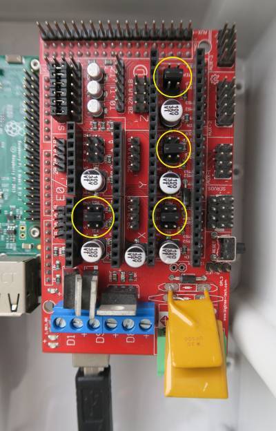
I found this difference between your setup of the RAMPS card and what’s on the farmbot site. You have installed jumpers under each of the motor controllers. I see what you are doing with the power pins, but I’m wondering about those jumpers under the motor controllers?