Hi Klim,
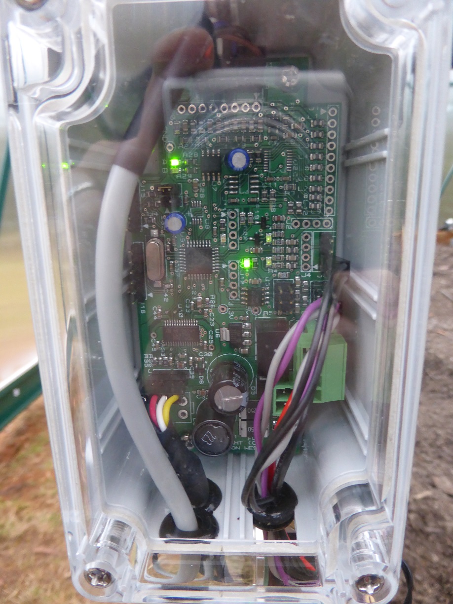
I designed a PCB to fit into a small ‘standard’ box which I could mount pretty close to each motor, so that the motor and encoder cables only had to route into the box. The PCB then just needs power (12V) and serial communications (RS485), which can be multi-dropped to all four motors.
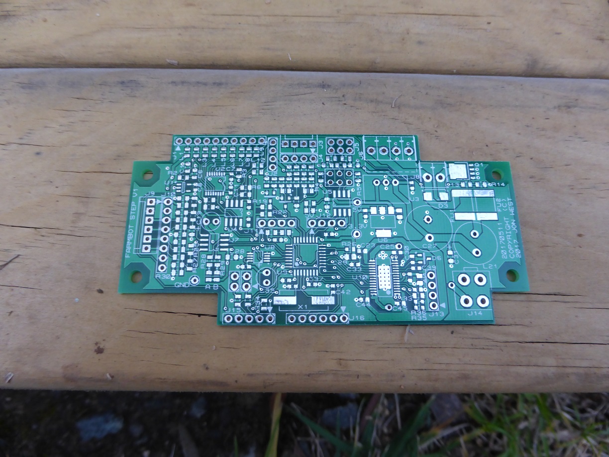
The PCB is approximately 100mm by 50mm, and includes:
- 12V to 5V/3.3V supply
- micro (STM32F334)
- RS485
- encoder interface
- two endstop sensor interfaces with wetting current
- stepper motor driver (L6474)
- one high current 12V driver (open drain)
- one 12 bit buffered analog input
- 8 bit buffered digital I/O
- buffered I2C interface (5V)
- emc/emi protection on all interface lines.
Not all components need to be fitted for all motors; only the Z axis motor needs the I2C, analog and 8 bit digital I/O for the tool head. But they can be fitted and used elsewhere too if desired. I use the high current output on the Z axis for the vacuum pump, and the X1 axis to driver the water solenoid valve.
The stepper driver is a modern type with software settable current limiting, so I can set the running current and then drop it down to a holding current when stationary. I also find that the stepper motor works better with microstepping, but you need to generate commensurately faster frequencies, which isn’t a problem if you use a software DDS technique.
I’ve connected the boards together using Modbus, only because I already use that protocol and have plenty of software that I can re-purpose. To control it I’ve simply used an existing board from another project; because it has a micro, RS485 interface and a USB interface on it. The software on this board implements the main G and F codes as detailed on the Arduino software GitHub page. But I’ve not used it much with the Rpi, so far only tested using a terminal sending the G codes. That’s why I’ve reached the point where I’m not sure whether to continue interfacing it into the Rpi, or whether to replace the Rpi software with something simpler targeted just at doing what I need.
The only real pain was making up the motor cables, in particular the motor encoder connector crimps are tiny (1.2mm) and awkward without the (very expensive) proper crimp tool.
If there was enough interest then I might be willing to explore manufacturing a few, but Farmbot themselves seem to be keen to keep using the Arduino platform.
Here are a couple of pictures of the PCB: