My young friend, who also has the awesome name of Rory, and I have decided to try and build a farmbot. We find it very cool what you are building and the way you are trying to make it all open source. If it is OK with folks, we thought we would post on this thread bits about our progress, challenges, what we are attempting to solve those, and random ideas for cool improvements. The goal being to share info that would be useful to others and at the same time get help from the community. Huge thanks to my friend Rick who got me going on this.
4 Likes
Ordering Parts
Let me just start by saying I can’t wait till I can jut go to the farmbot.io online store click “send me the whole thing” and be done. Most the parts I got from the sites suggested in the documentation.
We got the Plates from using the DXF file from 1.0 and had them cut by JP Metals in Calgary for approximately $200 US out of 3/16 aluminum. (not the 5mm in design). One thing we noticed is that seems to be missing the end bracket to mount the motors for the x axis. I think we will use the drawings from 1.0 to try and make one using a hacksaw and drill press. May try to cut with CNC router at some point.
The 1.1 drawings have a nice bent mental version of the Z motor mount but I think we will try and 3d print the one from the 1.0 drawings instead.
I have no idea if the stepper motors and encoders we got will work but we ordered the stepper motor from inventables part number 25253-01 ( https://www.inventables.com/technologies/stepper-motor-nema-17) and an AMT102-V encoder from digitkey (http://www.digikey.ca/product-detail/en/cui-inc/AMT102-V/102-1307-ND/827015). How the encoder mounts on the mortor is still an “miracle happens here step” but we might try to glue the encoder on to the motor. Any advice appreciated. The motor is a SM42HT47-1684B from smart automation (http://www.smartautomation.com.cn/ProductShow.asp?ArticleID=498). In looking for steppers, I found googling for 42HT47 useful as well as the page at http://reprap.org/wiki/NEMA_17_Stepper_motor
To run the PI camera over an HDMI cable, I got the “Pi Camera HDMI Cable Extension” from Petit Studio (https://www.tindie.com/products/freto/pi-camera-hdmi-cable-extension/ ). Perhaps a USB camera would be a better idea. Will see what happens.
The RAMPS shield seemed to be out of stock most places but http://www.sainsmart.com/ had them. All the stuff from sainsmart arrived quickly in nice case. I had not ordered from them before but I will use them again.
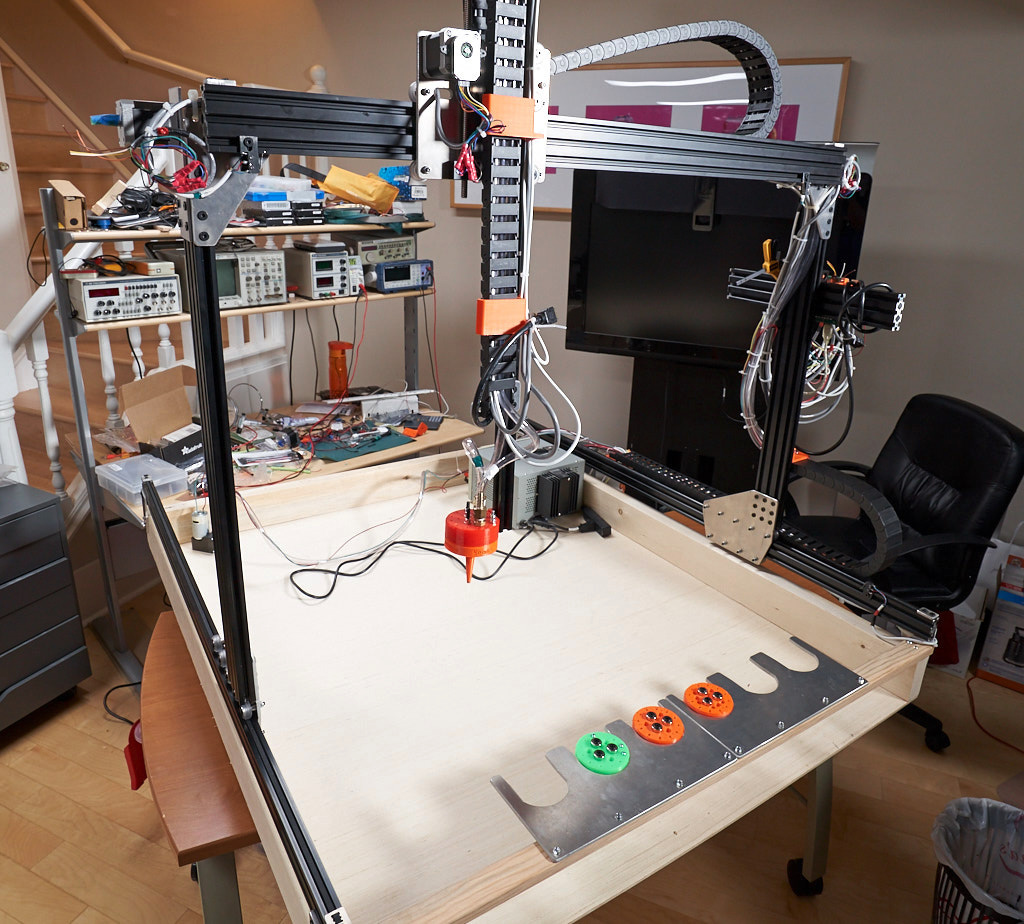
Building Tracks - Day 1
We set up the tracks to be about 1m by 1m space because it -20C outside right now and we plan to learn how to build this farmbot by making a mini-farmbot inside this winter then rebuilding it to a full size one outside in the spring. Questions that came up:
- How exact does the width of the track need to be from one end to the other?
And tip for next time, if the y gantry bar is 1m long, then that needs to match the distance from the outside of track on one side to the outside of track on other side.
Building wheels and mounts for gantry - Day 2
Anyone have good input on easies way to get the location of the wheels adjusted?
Building gantry - Day 3
Used lots of clamps and squares to try and get everything lined up square.
Building X axis drive train - Day 4
Because we love instant gratification and, well, we want to see it move, we are going to try and get the X axis all connected up to web site and moving before building y and z.
The DXF files we used to get the cut plates did not include the correct corner brackets. We used what we did get on one side. On the other side we used a drill press and hacksaw to make one
If I was doing this again, I would consider order the end plate that vikhyat had designed at Gantry Corner Bracket drawing
Setting up the Controller
Totally failed to get this to work until I attached a serial console to the Raspberry PI to see what is going on. Would be nice to have all the log data show up on the web site but even with that, probably need a serial console to deal with errors getting on WIFI and such.
Arduino firmware
Ran into bug (https://github.com/FarmBot/farmbot-arduino-firmware/issues/42) so can’t get the X asis moving. Will have to decide how to attack this problem. Looking at the code, I think I might try a patch that any time the pins for the X1 motor are set, the corresponding pins for the X2 motor are also set.
1 Like
Looks like you are making good progress! Thanks for sharing.
Yes, the v1.0 plates only include one x-axis motor mount because two x-axis motors were first implemented in v1.1 (v1.1 change log). We do have a flat plate version of v1.1, with drawings for the flat plates in that same folder.
The distance from the outside of track on one side to the outside of track on other side needs to be equal to the length of the gantry beam or less. The columns can be attached to the beam at any point, as shown in the gantry column installation instructions. Less is recommended so that there is room to adjust for the width of the tracks. You may also notice this in many of the videos.
V-wheel spacing adjustment instructions. I ususally start with the short-distance indicator facing away from the extrusion (widest spacing) and decrease until the wobble is eliminated.
Thanks for the patch. Since dual x-axis motor drive firmware capability is forthcoming, another alternative is using the dual motor pins for the z-axis on the RAMPS board and switching the X and Z axes in the firmware as a temporary fix. However, then the power is shared between the two motors, and both approaches require editing the firmware and uploading it via the Arduino IDE.
Great info - thank you. I did not realize there were flat plate designs in the onshape files for 1.1. I had been looking in the wrong places and I also found all the nicely organized 3d printing parts for STL export. Nice work and sorry I missed it before.
Water and Electricity - Day 7
Wired up Y and Z stepper motors. Do not have encoders yet. Set up a pump to supply water. We could not find the small barbs in the design so we took a 1/8 inch barb and drilled a 3/16 inch whole in the mount and pushed the barb into the mount with a vice. Then we connected another barb for the 1/4 water line to that one.
The holes to mount the UTM to the z axis are close together. The t-nuts in the 1.1 onshape design have a length of 10 mm which just works. Unfortunately the t-nuts we got (http://openbuildspartstore.com) are 15 mm long so are too long to fit between the two holes on the UTM. Might fix this by hacksawing a few t-nuts to be a bit shorter.
- One idea that came up was: why not have the barbs be just part of the 3d printed plastic so that the tube just pressed onto the tool mount directly and perhaps had a hose clamp?
And oh yah, we are having tons of fun with this
We are pretty excited that the current thing we have built moves and squirts water.
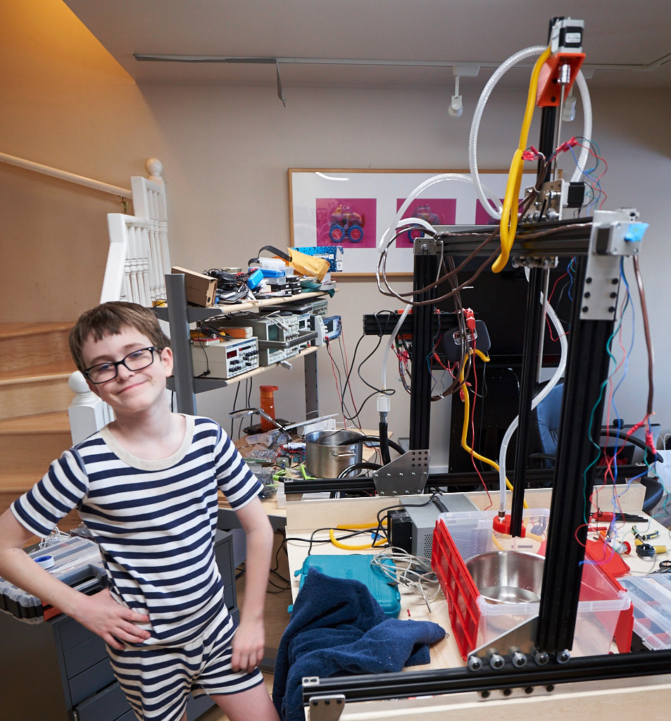
The only thing that would be better is if it shot weeds with a laser.
1 Like
I’m cheering for you Rory and Fluffy. I’m impressed by the ease you’ve had with the NEMA 17 and the encoder. I’m still stunned in the same position on that matter as i was a month ago.
1 Like
Calibration and Mounts - Day 8
We added the tool mount.
For the calibration of the pulses per mm of movement on the x and y axis we calculated how far 200 pulses would move. No micro stepping so 200 pulse = 200 steps. The step angle is 0.9 degrees so this would be 180 degrees or half a revolution. The gear has 20 teeth so in the half revolution, the belt would move the distance of 10 teeth. The belt is GT2 and the teeth are 2 mm apart so the 10 teeth worth of rotation would move the belt by 20 mm. So our system needs 10 pulses per mm in X and Y.
For the Z axis, the screw moves 8 mm per revolution. So 200 pulses is half a resolution and moves it 4 mm. So our system needs 50 pulses per mm in the Z.
We have not figured out how to set up the pulses per mm in configuration. Currently our x,y moves move 1/5 the distance they should and the z moves 1/25.
Tools - Day 9
3D printed some more tools and put magnets in the UTM and tools. Amazing how well the magnets work.
Cable Carriers - Day 10
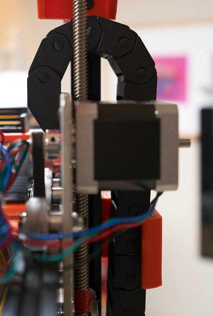
Added the cable carriers but ran into what looks like it might be a bit of a part problem (or perhaps design problem).
The design calls for the cable carriers with a bend radius of 28mm but what inventables is shipping has a bend radius of 38 mm and does not work.
The smaller drag cable that is 15x30 from inventables does have a bend radius of 28 mm so we are trying to use that for the z axis. Not sure if everything will fit. The mounting holes don’t line up and the carriers brackets are too wide but it looks like it will probably work.
Here is a side view of the z-axis drag cable where it mount at the cross slide plate. You can see the bend is tight with this 28 mm bend radius and no chance 38mm would work.
1 Like
Running Tubes & Wire - Day 11
Ran all the wires and tubes through the cable carriers. This was less
fun. If we did it again, I think we would run all the wire beside the
cable carries to get the lengths right, tape the stuff to the cable
carriers, then take all the carriers off and lay them mout straight on
the ground then pull the wires through them. We marked the cables with
the usual convention of Red=X Axis, Green=Y Axis, Blue = Z Axis and
yellow for the cable to the UTM.
The code to count the encorder pulses seems to miss some pulses when
run at high speeds so added end stop switches. Not sure what it is but
there is something I don’t understand, the first time you go to a
coordinate above a few thousand, it seems like the deceleration is way
too fast but future times to the same location seem fine. Suspect
there is some safety soft limit code that I don’t understand.
The actual encoders seems to be working fine. We currently have them
set to 48 pulses per revolution which the software will count as 4
times as many pulses per revolution which matches is close enough to
match the stepper counts. Ideally it would be 50 but that is not an
option. 100 is an option so in the future we might chance the software
to divide by two and use the 100 pulse per revolution setting.
Programming - Day 12
We have a mostly complete minimal farmbot.
Can’t figure out what is up with calibrate command but it does not
work for us so we just hacked the Arduino software to do a home when
it receives a calibrate command instead. That’s all we need for
now and can try calibrate again once it seems to work. Patch to do
this is at
Fixed a few other issues in Arduino software.
The backlash in the Z axis is pretty brutal because as the whole flex
coupling gets stretched out when it is moving one way and compressed
when moving the other way. In the future, might be worth considering making a
bracket with bearing and collets on Z axis screw to take the drive force instead
of using the stepper motor. We are having a hard time getting the z
home to be consistent enough to be able to put a tool back in the tool
slot.
Having a very significant issue where the robot is moving around for awhile
then just decided to reset wherever it currently is to be the origin.
No idea what is causing this.
The vacuum pump we have is too wimpy to pick up much.
Things ToDo
- Add camera
- Better vacuum
- Wire up soil sensor
- Add encoders for X and Z
- Add motor covers and boxes so it can go outside
- Add the detect wiring for all the tools
regarding the tubing this would be an option i guess. not sure what it translates to in english:)