Hi guys, I as DIYer am not fully satisfied with the encoders. Their cables take lot of space in cable chains. The drag chain outdoor cables are really expansive (LAPP, UV resistant drag chain cable). If you need additional things as end stops or even talk to your tools on UTM you need more cabling and RS485 which is obsolete. Motors with encoders are also expansive.
In comparison there are very cheap CAN bus modules, Arduino pro mini boards and high-end magnetic encoders. I also need to talk to UTM tools like lens-weeder, drum seed tool or laser weeder.
This leads me to idea: What about CAN bus for encoders, end stops and UTM ?
Is someone else interested in development of such feature?
Very interested in your progress, one of my biggest lessons in canbus has been susceptibility to interference and subsequent communication interruptions, the fix in a large scale distribution facility was to use a common ground wire. My joke at the time… why didn’t we just wire up the controllers and switches.
I am running the CSI camera over Ethernet cable (gigabit LAPP one) on 3m long Y arm. I experienced few years of issues with this idea (can not say prototype) and finally correct grounding and EMI stuff did solve it. My issue solving diagram was more crazy then the real solution. I understand you but if the CSI camera works then I see no reason why CAN bus should not.
Let’s try but this could be great jump farmbot…
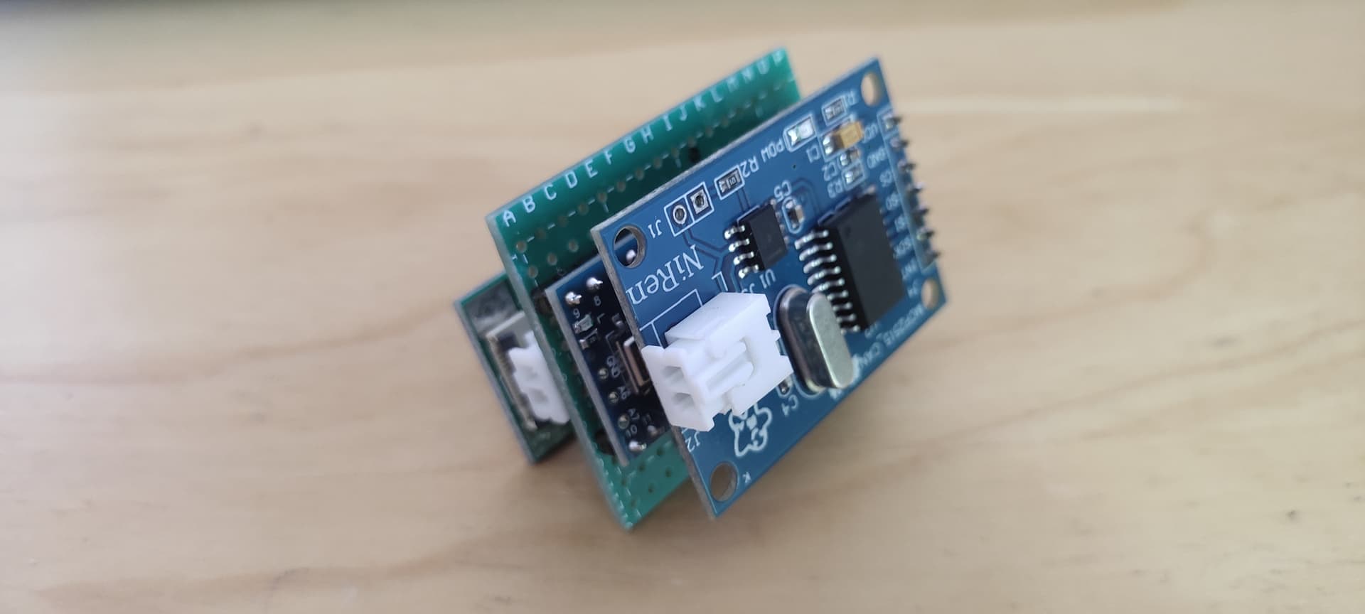
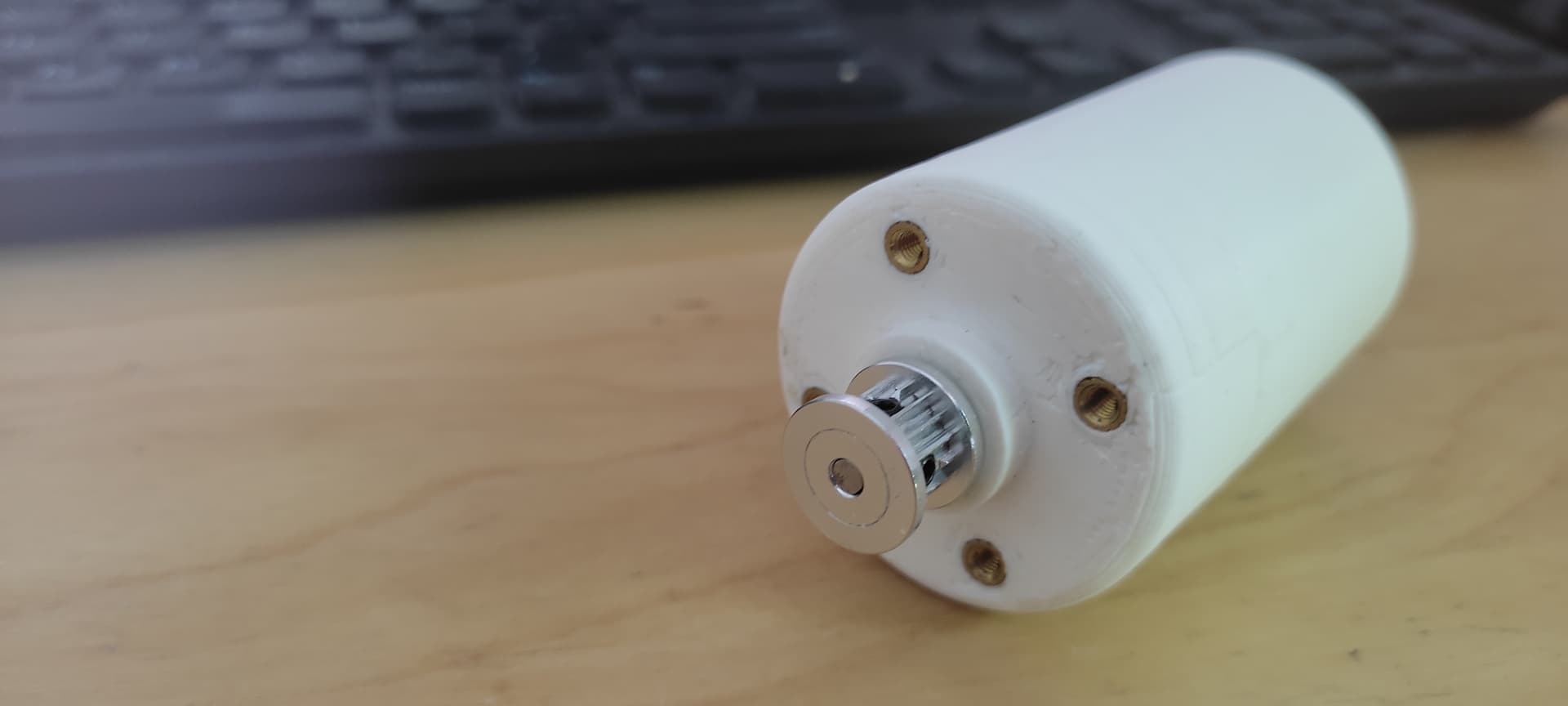
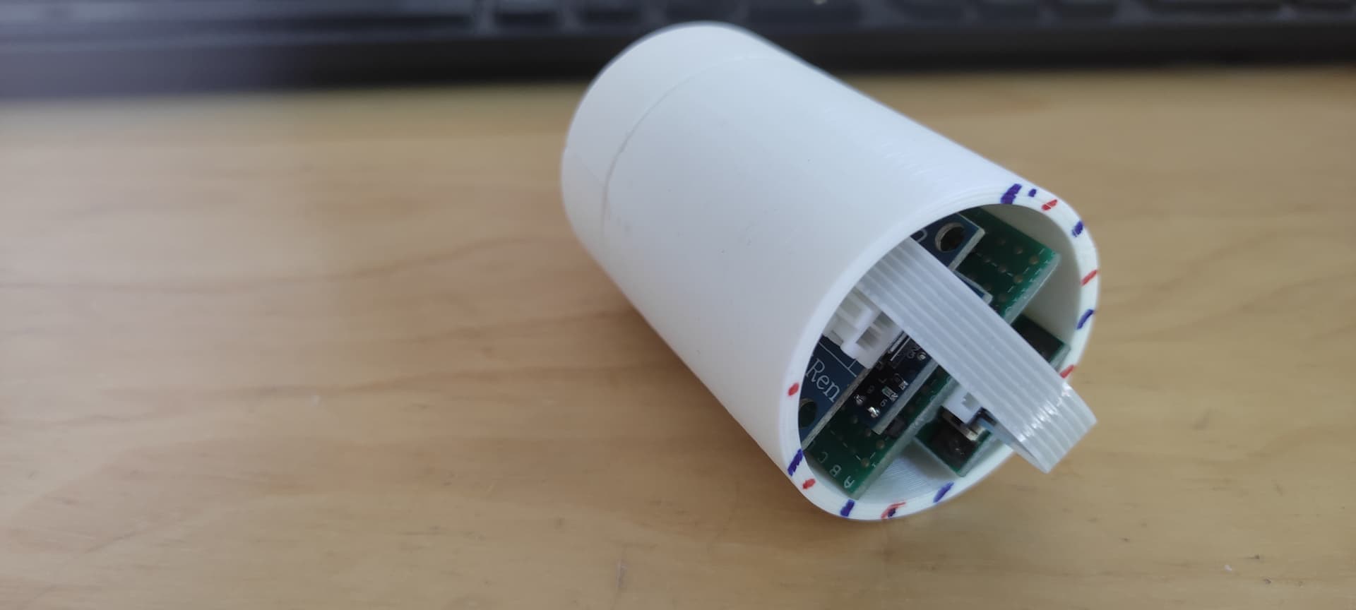
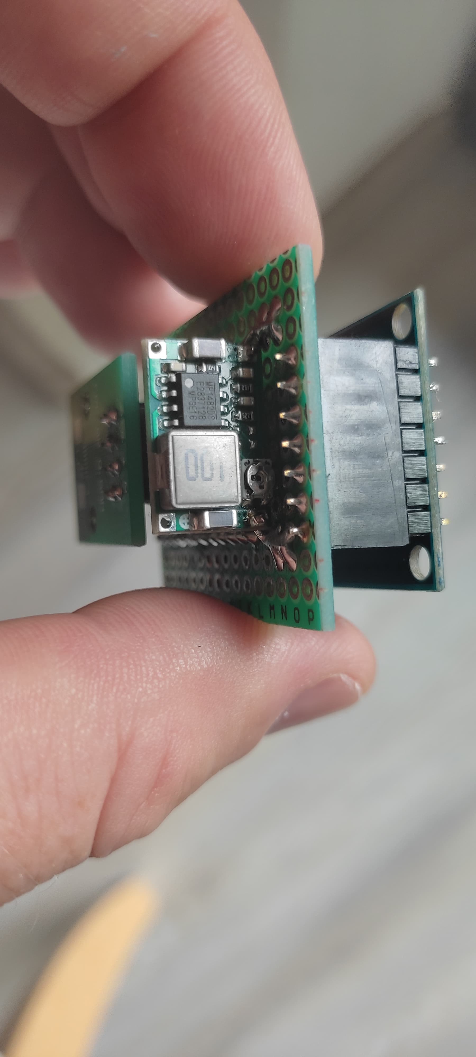
Very cool prototype @jan.janson! We have been slowly contemplating a very similar electrical architecture overhaul for Genesis v2.0 (still probably several years out). Here is the gist of what we’re thinking:
Integrated driver/motor/encoder units. So, moving the stepper driver from the Farmduino to the motor/encoder unit itself. On the back of the motor we would have a PCB with the driver, a magnetic encoder sensor rather than the current optical one (saves a lot of cost and is more than adequate for FarmBot’s needs), a 2-pin micro DIP switch for selecting the axis, a MOSFET for a daisy-chained ‘dumb’ peripheral, pin headers for endstops, and an STM32 microcontroller.
This microcontroller would run an amalgamation of the current rotary encoder firmware running on the Farmduino’s STM32, as well as some of the driver/pin control logic from the current farmbot-arduino-firmware.
The driver/motor/encoder units would be connected and networked to the main electronics box via a single 4-wire cable and communicate over CAN. So the cores would be GND, 24V, CAN Low, and CAN High. There are other potential protocols/physical layers to consider PoE+, Differential I2C, BLE, USB-C but CAN seems the most appropriate.
The main electronics box would be downsized and the new Farmduino would actually not be an Arduino at all. Instead it would essentially be a large breakout board for a Raspberry Pi Compute Module.
FarmBot OS would then replace the farmbot-arduino-firmware and G-CODE middleman and orchestrate control of all the motors and peripherals via the CAN network.
The advantages of this architecture would be to:
As you mentioned, eliminate a lot of cabling, which would allow for much smaller and lighter weight cable carriers which reduces cost and improves performance (less mass to move around).
Move away from the slow and memory constrained Atmega 2560 and towards the orders of magnitude more capable STM32 and Pi hardware. This would also allow for movements to be non-blocking, so we could do things like Rotary Tool load monitoring in a less hacky way.
Eliminate an entire codebase (farmbot-arduino-firmware) by moving a small amount of low-level stuff into the STM32 and the rest of the things into the Pi where it will be easier to develop and maintain using a higher level language than C. By eliminating the G-CODE layer we’ll eliminate a lot of complexity and shortcomings that have come from its use.
Distribute heat-generating electronics throughout the machine.
Save a lot of cost by eliminating the optical rotary encoders which account for 80% of the cost of the current motors.
Daisy chaining peripherals will allow for much cleaner and shorter cable runs: X1 → Solenoid, X2 → LED Strip, Y → Vacuum Pump, Z → UTM (maybe).
There are some other projects I have been following that are developing network controlled integrated closed loop stepper motors. Check them out:
Anyways, all of this is a long ways out. Its just an idea at this point, but I am happy to see others in the community thinking along similar lines. Definitely open to suggestions and personal experiences in this area from any other electrical/mechatronics engineers out there.