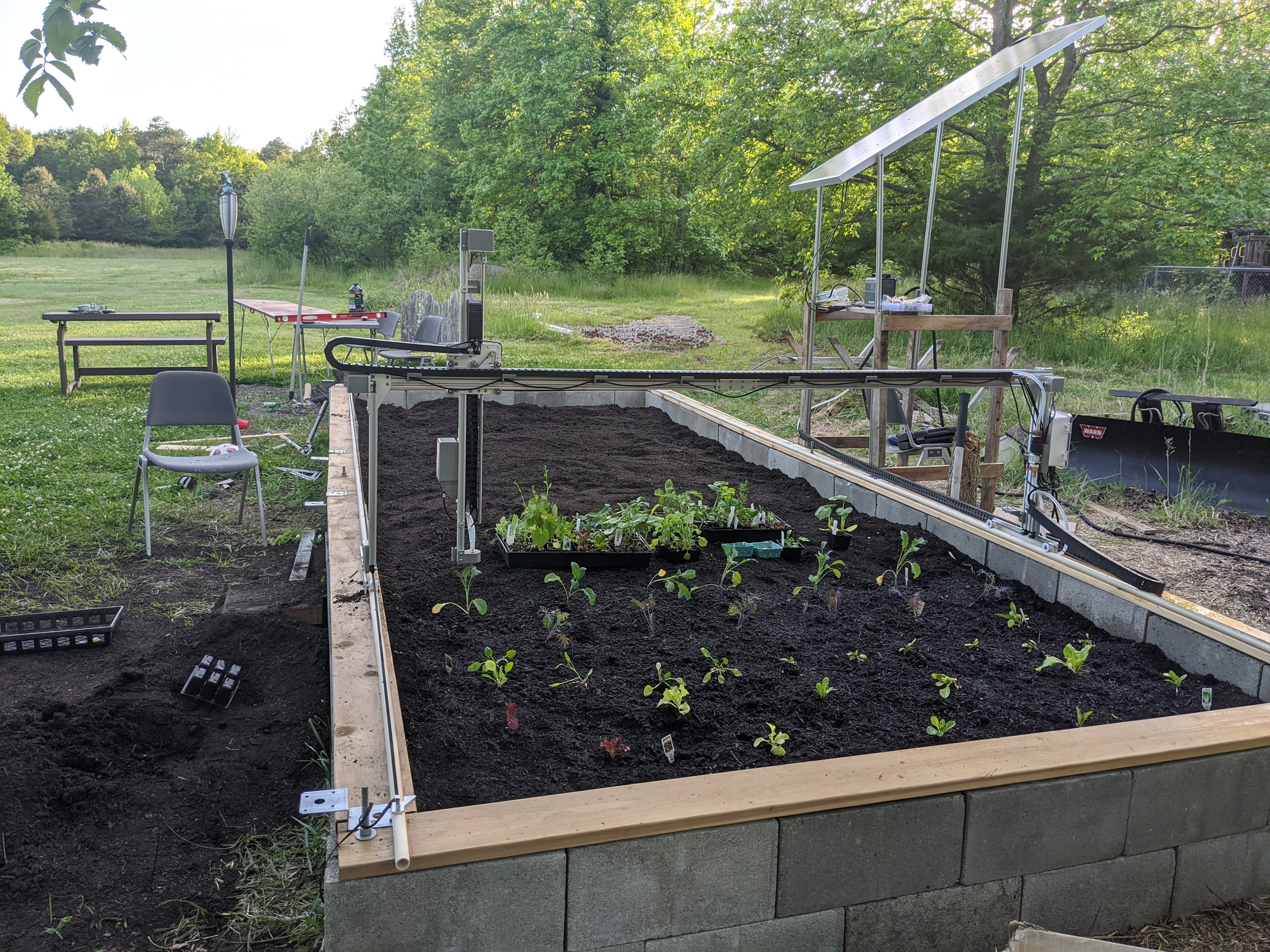
I mentioned in a post somewhere that I was experimenting with a different X-axis track design on the Express XL out of the box. We got motion control up and running yesterday and the tracks are initially a success. The tracks were laid out with snaplines that were measured to be parallel. The concave-U-wheels replace just the black plastic of the factory idlers. All bearings and hardware are reused. The belts fly over the wheels to raised anchor points.
9 Likes
With a beefy PV solar panel as well 
Am curious how you’ve fastened the tube tracks ?
Right now, I have them fastened with deck screws. I counter sunk the hole for the heads which are at the top surface of the tubes. Button-headed screws would have been better but the deck screws were lying around  .
.
Yes I got a 160W panel. The battery is too small to carry me through the night though.
1 Like
Nice idea very cheap and simple.

@roryaronson and @Marc,
Alright, I think I have a moment or two for the engineering rationale. Upon receiving the Express XL kit my assessment was the same as @markgregory8; that the materials (idlers and wood tracks) were insufficiently robust and the wood movement would be significant. Even though I made a CMU base I still expect significant settling, not to mention the wooden sill swelling and contracting. I want to be clear that I truly appreciate the effort to make a lower-cost model but my experience tells me this will not work.
At its heart, this problem is a tug of war between a perfectly aligned, rigid system and one that allows for sufficient forgiveness to permit self-alignment. Most ‘perfect’ solutions are burdened by cost and maintenance. Additionally, the failure mode of a rigid solution is a systemic failure (binding or tearing). Most forgiving solutions are burdened by the loss of precision and added complexity. For example, a system employing closed-loop control of driven wheels (not on a track) would be perfectly forgiving but rather complex. Interestingly, @markgregory8 went with a somewhat more rigid solution and I went with a more forgiving one. The flexibility of the CPVC pipes are indeed part of the design. The next post will explain that design in detail.
3 Likes
Hi Aron,
Really interesting to hear your thoughts re allowing movement so that it can self-align. I hadn’t thought of that! I have the Genesis 1.4 so it’s a slightly different kettle of fish. Your farmbot is much wider and so I would think it would be more difficult to get it working. Well done!
I was lucky when I created my solution as at my school, we had over-purchased on 100mm x 10mm aluminium and so I had a heap of that to use as a frame. That would usually cost a fortune but we had it there so that’s what I used. Some 2060 T slot would work just as well and be more sturdy I would think. I didn’t weld the joints, I just used nuts / bolts and brackets.
The frame is indeed rigid but it floats on top on the timber in channels that gives it a good 50mm to move side to side without upsetting the alignment of the x axis rails. I checked the alignment of the rails a couple of months ago, about 12 months from our first Farmbot success and they were only 0.5mm out of parallel so the movement was nothing. The problems that I’ve had since we originally got it working have mostly been self inflicted.
Regards,
Mark
I 100% agree that the Express kits, particularly at XL and Max lengths are simply not usable as designed and a fix is needed.
The concept of running directly on the wood of the garden bed is a good one, but the execution is lacking and fails to account for the fact that it is extremely difficult to get wooden beams exactly straight and 100% aligned over any significant distance.
In my situation, with a 4.5m x 2.7m bed I had to use 2 x 2.25m wooden beams for the 4.5m side because it was impossible to get 4.5m lengths into my 7th floor apartment terrace without an expensive crane.
Many of Farm.bot’s customers are in similar situations and one of the big appeals of the Farm.bot is being able to grow more in a limited area than a traditional garden.
While I was very careful with alignment and put in cross support beams at the point of joining the two 2.25m beams, 100% alignment was impossible to achieve.
I hate to imagine the problems over 6m with an Express XL and 18m with an Express Max!
I also think that the Genesis 2040 V Slot Rails solution is not a good one because I will face the same difficulty aligning the V Slot Rail which attaches to the side of the bed.
A far better and (these days) cheaper solution is the use of MGN12 linear rails, which mount directly on top of the wood and can be easily aligned with a string line as long as the mis-alignment is no larger than the width of the top of the wood (in my case 45mm).
I priced out the cost of moving to the Genesis V-Slot solution over 4.5m sides as $450 using Farm.bot’s BOM and $390 if using OpenBuild’s (substantially cheaper) 2040 V-slot extrusions.
I have found 800mm MGN12 linear rails for only $24 (after discounts) per 800mm so that it would cost only $264 for 2 x 4.5m. https://www.banggood.com/Machifit-MGN12-800mm-Linear-Rail-Linear-Guide-with-MGN12H-Block-CNC-Tool-Linear-Motion-p-1288479.html?rmmds=cart_middle_products&cur_warehouse=CN
Linear rails directly mounted to the wood avoids the cost of end & joining plates and the wheel plate and v-wheels.
They offer superior rigidity to V wheels and should be less prone to blockages from dirt and plants as the bearing run is on the side of the rail rather than on top.
Also the thermal expansion coefficient of steel (10-12) is half that of aluminium (21-24) and much closer to that of pine wood (5). https://www.engineeringtoolbox.com/linear-expansion-coefficients-d_95.html
This should lead to less issues with thermal expansion and contraction.
There is a glut of linear rails in China and I would have thought that Farm.bot could order a container of them very cheaply.
In the 3D printing world everyone is going with linear rails now because they have become so cheap.
2 Likes
How are you coping with thermal expansion of the PVC pipe?
PVC has a very high thermal expansion coefficient (54-110) vs pine wood (5) Steel (10-12) and Aluminium (21-24).
I would have thought that the PVC pipe would serious bow in hotter weather.
https://www.engineeringtoolbox.com/linear-expansion-coefficients-d_95.html
1 Like
In 95F heat there is no visible bow in my setup. I don’t know why because your reference is correct. Understand that my design allows for some flex with the bot basically wanting to spring to the center. The anchor points along the length are never in the same location on left and right right rails so the Farmbot frame can distort the opposite rail as needed.
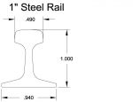
All that said and along the lines of your suggestion @apshamilton, I would like to offer yet another solution. @Marc have you considered live steam scale (ride-on miniature steam train) track. At $45 US for 20ft (6m) I don’t think you can beat it.
https://www.rmirailworks.com/sc/ss_mb.cgi?storeid=*1cfc4ae590eaf121c16b472aa0b4e108&ss_parm=Acac7c0cb2cde645fbede9467eda97e06
3 Likes
Interesting.
What spacing are your anchor points of the deck screws? What is the offset left and right?
I like your mini train rail idea.
@markgregory8 / @aronrubin,
I was just reviewing this thread and I ordered an ExpressXL and I also found that the X- Axis was almost unusable. It work for awhile and then starts to go awry.
I was curious how the CPVC turned out and I thought I would share my thoughts and ideas.
A couple years ago, I built an MPCNC (Mostly Printed CNC) It runs on 3/4" EMT conduit as well as a couple other dimensional tubing sizes. I used the EMT for my MPCNC. It worked so well, I thought why not adapt it to be the Farmbot rail system.
I Have reprinted a new set of corners and all of the pieces for the Z carriage. I am modifying the trucks to have an integrated plate for the aluminum risers. Initially I will attempt to use the MPCNC for the X-Axis and see how it goes, I am also contemplating a redisgn to allow the Y-Axis to be two 3/4" conduits on a double truck running along the X-Axis. My current concerns are attaching the risers to a 3d printed truck on the X-axis. by switching to a double conduit Y-axis, I could raise the legs and run the track higher, essentially eliminating the possibility of the Y and Z axis’ and being top heavy. Take a look at the MPCNC (It’s easy to search for) and if I get mine setup, I will post some pictures
Thanks,
Roark
1 Like