Hi!
Im about to build my express now and am facing the same problem as the last time i tried ![]()
Does anyone know how the emergency stop button is connected to the connector? (P8) I mean a wiring diagram of how the no/nc is connected to the board.
Hi!
Im about to build my express now and am facing the same problem as the last time i tried ![]()
Does anyone know how the emergency stop button is connected to the connector? (P8) I mean a wiring diagram of how the no/nc is connected to the board.
Hi @jakeelee
Which Express device model (version) are you asking about ?
There are FarmBot Inc. schematics publicly viewable which answer your question ![]()
Hi ! I know that there is schematics of this but im not sure about what state they need to be in.
I just wonder if someone could just draw a little diagram with the no/nc connected to the endstop inputs. Its the V1 version
Well, I’m confused . . your first question was about E-stop wiring, and not about endstops !?
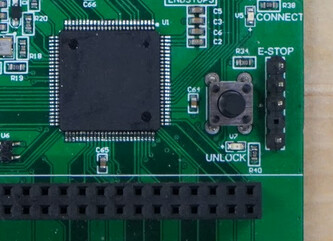
Here’s P8 on the Farmduino Express where the E-STOP button wiring attaches
Here’s the P8 wiring drawn in the PCB schematic
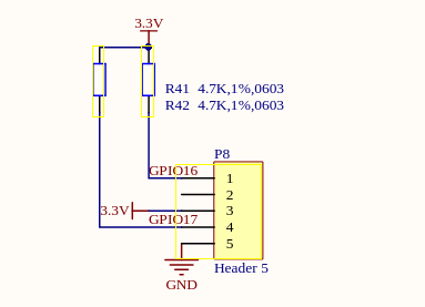
From the FarmbotOS code, E-Stop is GPIO 16 on the Raspberry Pi Zero W computer.
The code will trigger on Rising-edge of GPIO 16 input. It seems the common wire at the button will be GND (0V) so you’d use the NC side of the button wired to pin 1 of P8.
This topic was automatically closed 14 days after the last reply. New replies are no longer allowed.