Roving agricultural CNC:
https://hackaday.io/project/53896-weedinator-2018
Hi,
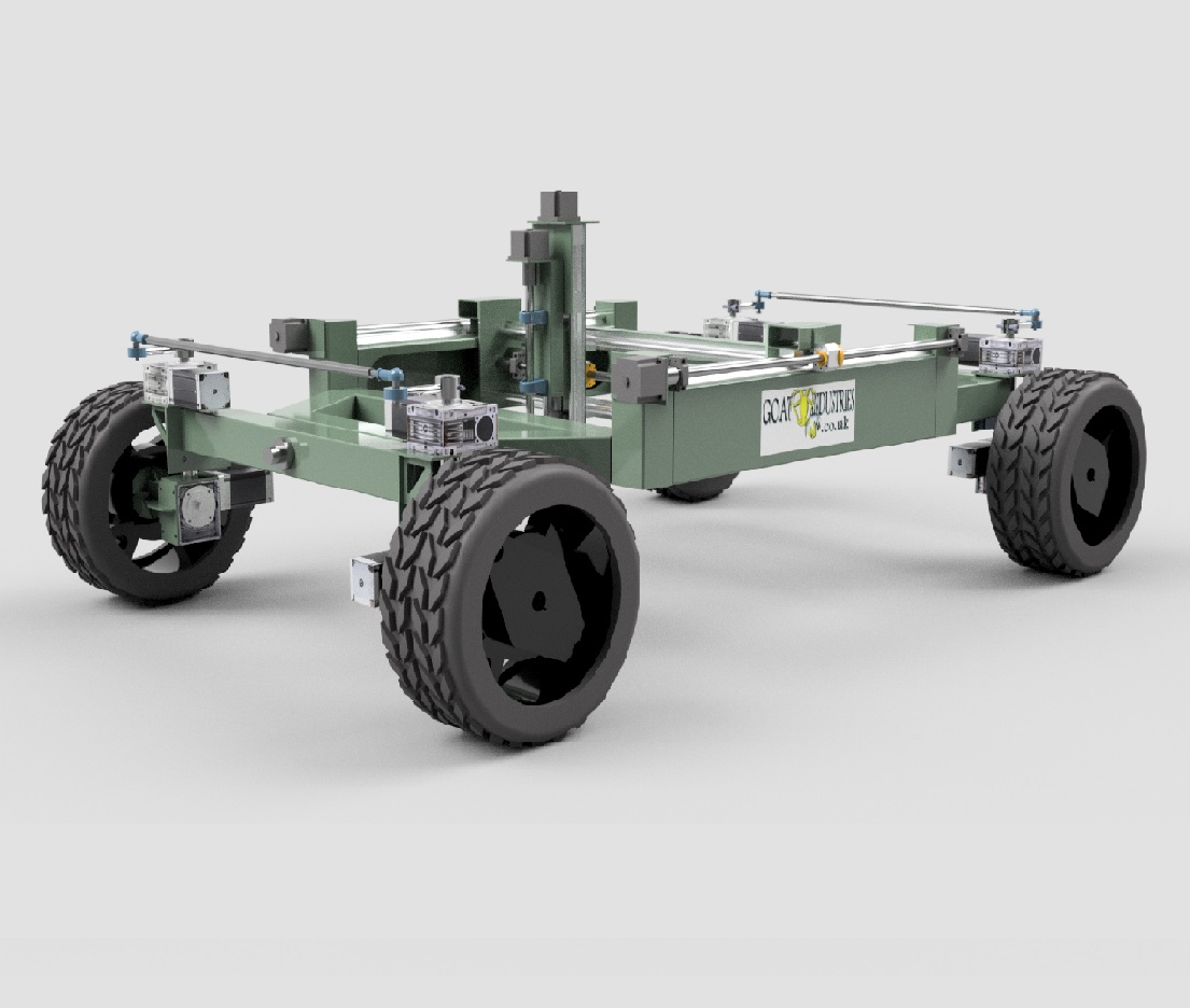
I found a picture with a farmbot on wheels (attached).
Does there anybody know about this project?
Leopold
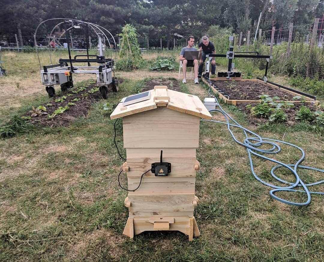
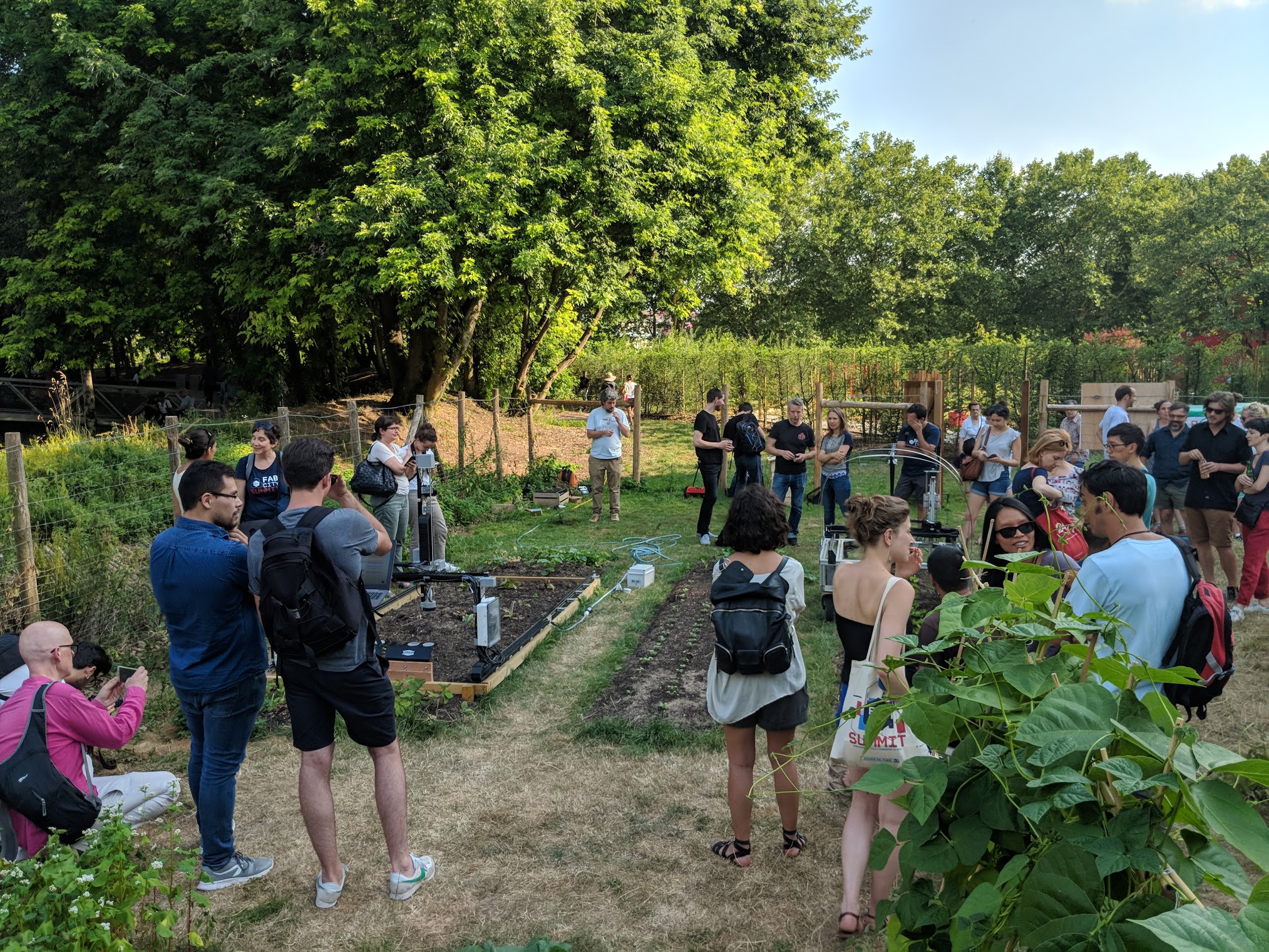
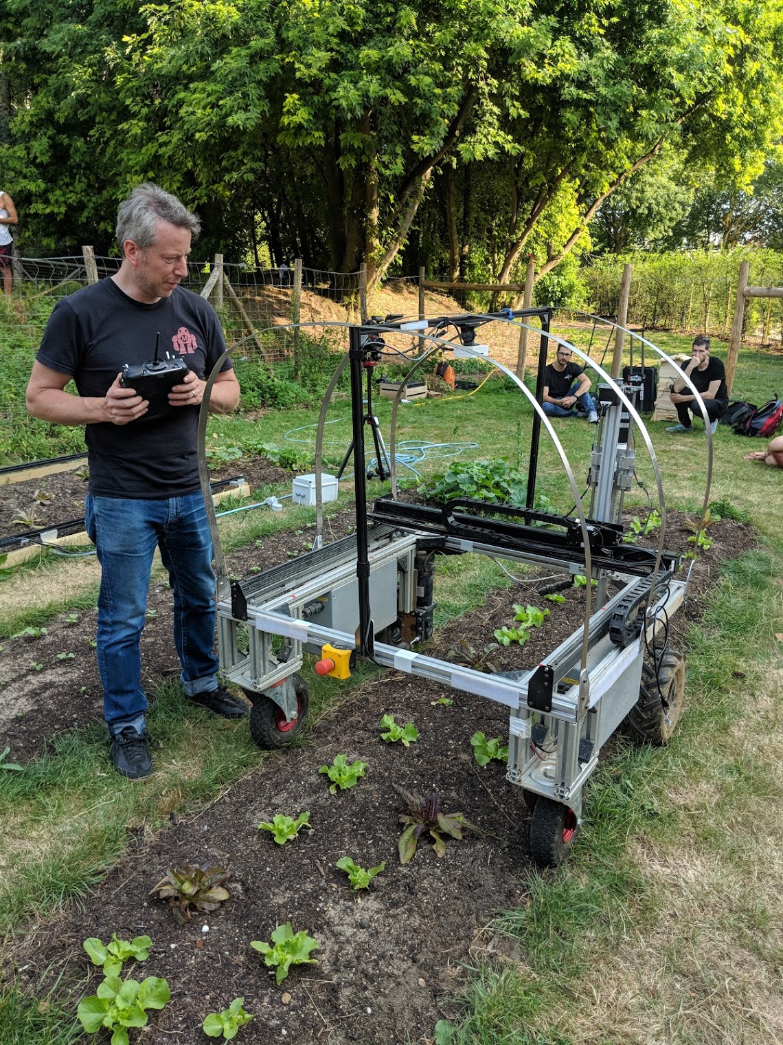
That is the open-source ROMI Project on the left, an Open Source Beehive with Buzzbox in the middle, and a v1.3 FarmBot Genesis on the right.
The installation was part of a public demonstration of the technologies in the La Villete Park in Paris, France earlier this month, which was a part of the Fab City Summit conference. I spoke at the conference and got to meet the whole team behind ROMI. There may be some collaboration potential in the future!
Hi Leo
Do you have any updates on this?
Thanks
I think long rails with QR codes printed every few meters would be a good next step.
For longer term rail-less operation I was wondering if a laser would be useful? Position at one end of the bed pointing at the farmbot, as it moves the bot keeps the laser point on the target. If it wanders left the laser moves from the target spot and the machine corrects its course.
hi there.
New to the forum, been following farmbot for a while, silent fan 
I’m the proud owner of a veggie garden of about 150m² so a gantry-style system would be massive…
I’m looking to build a “little helper”. I mean a little robot that has the same footprint as I do, with a robotic arm of about the same length mine, to help with some routine tasks.
I’m (slowly) working on a low-budget wheeled robot, us wheelbarrow wheels, salvaged DC-motors from car windows, working on bicycle-chain transmission pulleys from PVC plate.
For the robotic arm I envisage building it with 2mm steel wire, in a wire-frame composition, and using stainless steel wired rods (M6) as axis and bearings. cheap but probably strong, light and mainentance-free. motors will be the windshield whiper motor from that same donor car. Did some tests and I’m convinced I can produce this once I get design done.
Positioning is the main challenge.
I use RTK-GPS professionally (2cm accuracy) but those are expensive, complicated and unstable system (we use Leica GNSS sensors). It needs good satelite reception so under trees or close to walls, precision is gone.
RTK-GPS requires two high-end sensors and some complicated software to get precision to 2cm.
Another method is D-GPS (differential GPS). This can be implemented using cheaper sensors, should get accuracy of about 5cm.
OpenCV sounds too complicated for me. I tested the PixyCam because that takes care of the image processing, but I feel it’s very sensitive on changing light conditions. Would be a shame if the machine could only operate at night with controled lights 
Another system that caught my eye is https://www.pozyx.io/
This uses local ultra wide band beacons. A 600€, this is unfortunately over my hobby budget…
Also interesting is technology used in Toadie, a grass cutting robot using SLAM (Simultaneaus Localisation And Mapping) using the Kinect sensor if I’m not mistaken. Also here, I think software is too challenging.
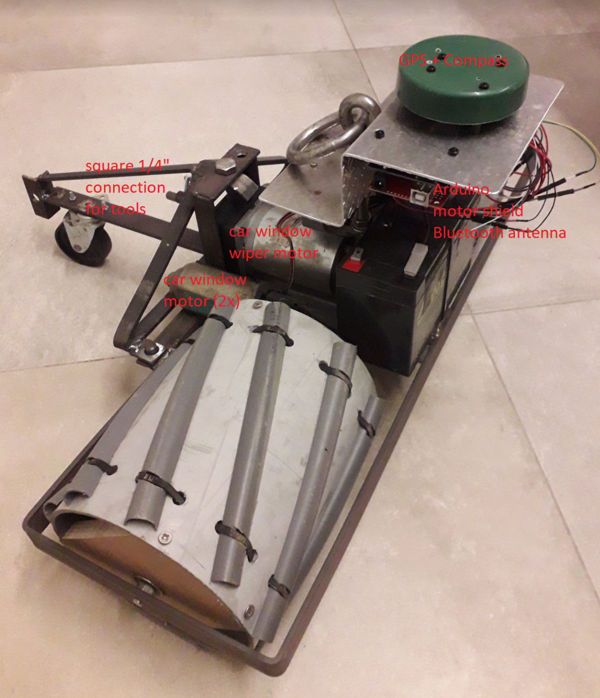
Anyway, I now have a first set of wheels running on batteries with a joystick and arduino (leaping to the future, I named it “Farmbot Unchained”).
Next step will be adding a 7€ GPS receiver to the bot, another to a base station and see how D-GPS behaves in real live…
I’ll probably make a mix of three sensors:
So, I have plan!
Looking forward to winter to find time…
Hey sounds great  ! Do you have some pictures?
Ok, one image per post…
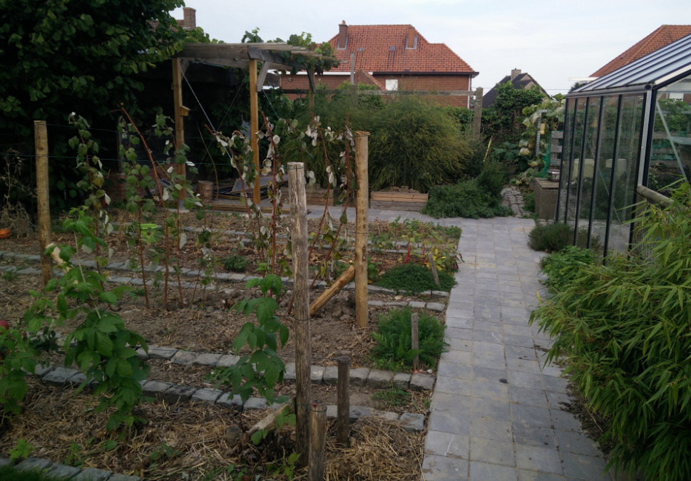
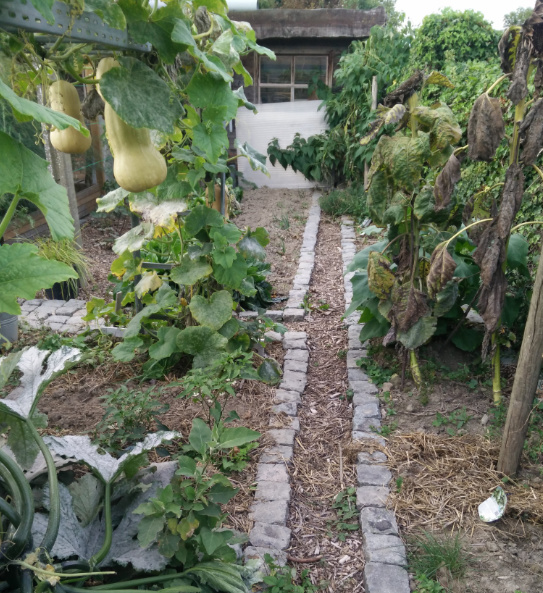
veggie garden, pretty empty now after harvesting the main crops, will sow winter crops shortly.
beds are 120cm wide, 60cm paths separating them, that’s my footprint and range…
During summer, most crops extend over these paths but during that time, I have no work exept harvesting.
I have 6 beds where I rotate crop groups, and several beds with perennial plants (herbs, white asparagus, several root crops, …)
I also have a small aquaponics system in the greenhouse.
this produced only one miserable cherry tomato all year…
pH was too low and I probably had a iron defeciency, possibly a calcium overdose that blocked potassium intake. I’m still searching for good information on defeciency charts.
The pump probably consumed 150kWh of electricity.
My brother has a system that flourished beautifully over the last 3 years so I’ll give it another shot next season. I’m mainly curious to see what temperatures I’ll be able to maintain throughout winter because of the water volume, thermal isolation and a soil heat exchanger that’s burried underneath and has been storing heat all summer.
Crap, I can only do 3 replies as new user, Please reply if you 'd like the picturs of the actual bot…
Looks great! Please post some pictures of your bot How does your soul heat exchanger work? 
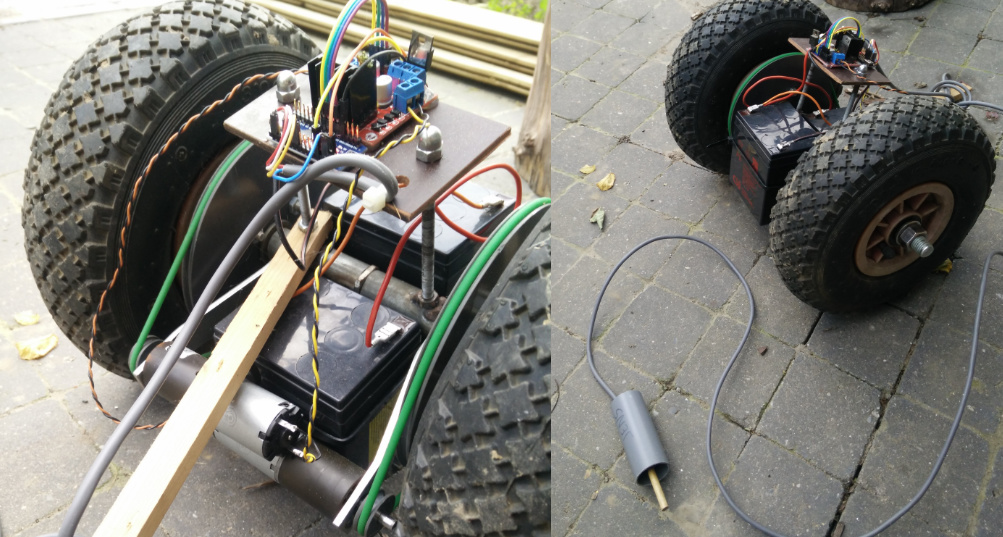
Joystick controlled “first set of wheels”
I crafted the pulleys lathe-style on my bench drill. Do not try this at home…
Doesn’t work well, the O-belts slip in the pulleys, this bot can’t even get over the 3cm step to get out of my shed. I’ll replace this in the next version with car window motors and bycicle chains.
This version will probably do for testing how D-GPS works in my garden, I’ll also add the 10 DOF sensor. Unfortunately, this version does not yet have rotary encoders on the wheels.
Salvaged motors:
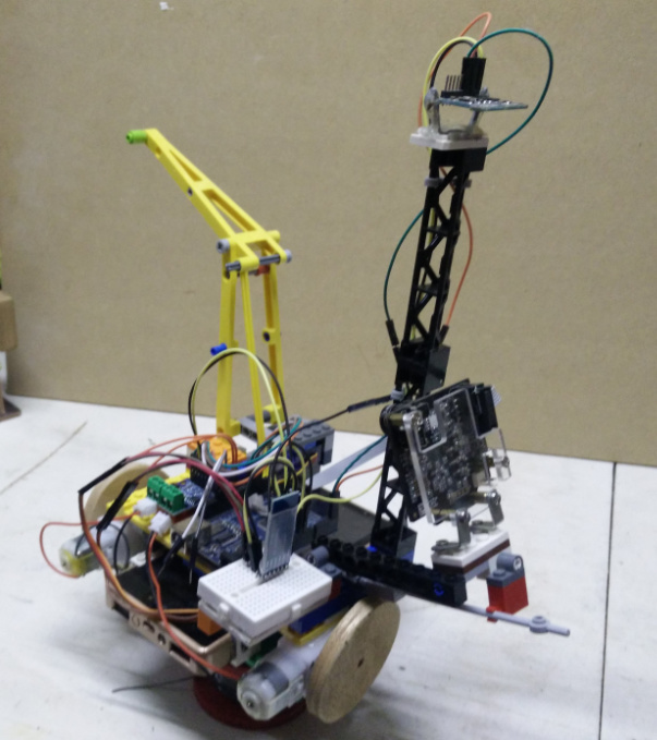
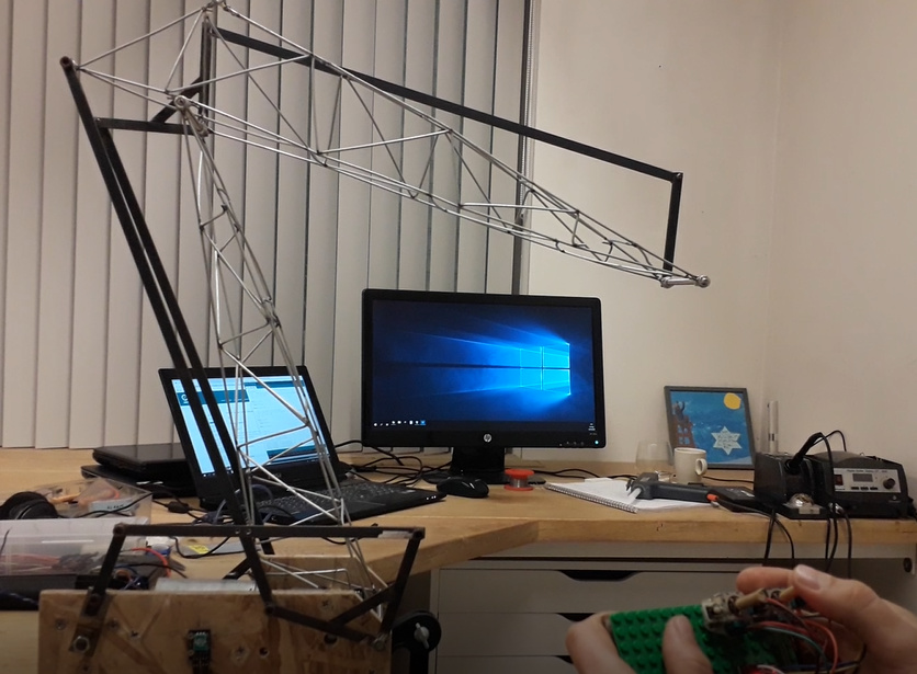
Here’s a pic of a previous test with 10DOF sensor and pixycam. Built with Lego blocks. This is the rough shape I imagine my bot: a robotic arm with two DOF.
30cm above the wheels, an antenna for GPS receiver and 10DOF sensor.
my lego skill are a bit rusty, the whole thing was pretty fragile…
I had hoped the pixycam would recognise the cilinder block at the end of the yellow arm and the bleu block in the middle, to get feedback to the positioning system but that was’n stable under changing light. Maybe software updates or new releases will improve that but I’m not counting on it.
I currently plan to skip all vision system, except for a camera for timelapses because that is pretty cool!
The 10DOF sensor allowed driving in a straight line based on compass.
Untill it drove over a steel reinforcement bar that’s under my desk… then it went bananas. That took me some time to figure out…
BTW, the soil heat exchanger from the aquaponics is just a 40mm pvc tube buried in a U-shape about 30cm below the bottom of the pit. so about 1.2m below ground level and 3m long. a part of the drain from the growbed passes through that tube. It probably worked well to maintain water temperature low during summer (never got above 23°C), now hoping it will keep temp above 10° during winter.
Hey @TomC that looks great, loving your prototypes already 
How come that you have so much time to work on these great things? I wish I had
Please keep this thread alive with all of your new prototypes and developments, its great!
I managed at least to control my bot via openhab, reading the soil moisture with a standalone capacitive sensor sending the data through an ESP8266 to openhab. This is then taken into account plus the weatherforecast for the next day. If the probablity of rain and the rain level is below a set threshhold and the soil moisture is below 88% the bot will water the garden. Everything else is not really working satisfactory on my bot (soil moist measurement through bot, seeding, weeding), so I am only using a very expensive device to automatically water my vegi garden plus having something to play around with 
Those prototypes are about a year’s worth of hobby time, not all done last week…
I try to avoid spending time on traffic and TV, that helps a lot!
I tried openhab for a while with Hue lights but they behave strangely, blinking about 20 time at certain changes of the hour. Not cool when that happens in the bedroom in the middle of the night…
Now I come to think about it, all of my IoT-trials ended badly …
My bot arm is getting pretty close a working prototype, stay tuned
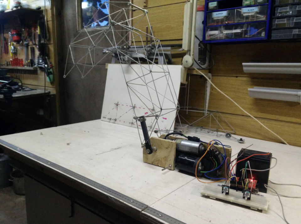
Alright, proof of concept for robot arm fabricated with steel wire and car window wiper motors is a partial succes.
I wanted to make something like this:
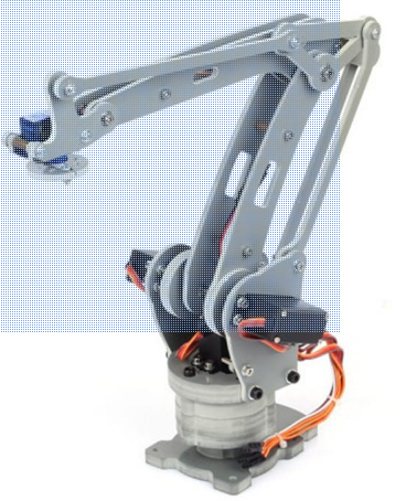
but bigger, cheaper and stronger. partial result is:
my production process was:
Learned a lot:
All and all I’m stil optimistic about the concept. however some changes are required to create something that may actually work…
Alright! Triangles are so cool 
Second prototype lifted 1kg and has a range of about 80cm. I’m optimistic this could do 2kg with some more tweeks and a fully charged battery…
There’s no 3D printed or laser cut parts but I do think this could be made in a makerspace or any garage in fact.
“microwave oven transformers spot welding” can probably be replace by lashing and some sort of resin. There’s some hot-rolled steel section in there that I stick welded but those can probably be made out of wireframe too.
positioning is not yet done, I smashed the encoder during a serial communication software test…
next up:
it’s been a year since I posted on this topic but I did make progress !
summer prototype:
I took the leap and payed 300€ for an RTK shield, and that is just great! cm precision and fast.
current prototype:
I ditched the compass, it’s a mess trying to avoid interference without wobbling on a 30cm post, now that I have cm GPS, I can calculate heading feedback from GPS.
Currently I’m struggling with motor control. the feedback from the encoders is 1 pulse per 2.5cm, that’s way to slow for PID. Also I want left and right cross control. For instance, if the left encoder shows there’s no movement, it needs to increase power of the left motor, but it also needs to slow down the right motor so it doesn’t go of track.
I’m sure this has been done before but cant’t find ready-to-use code so I have to write custom control. not fun…
Great project Man!!
We want to put a FBMAX onto rails, but looks like we’ll now go with wheels 
Love what you are doing!