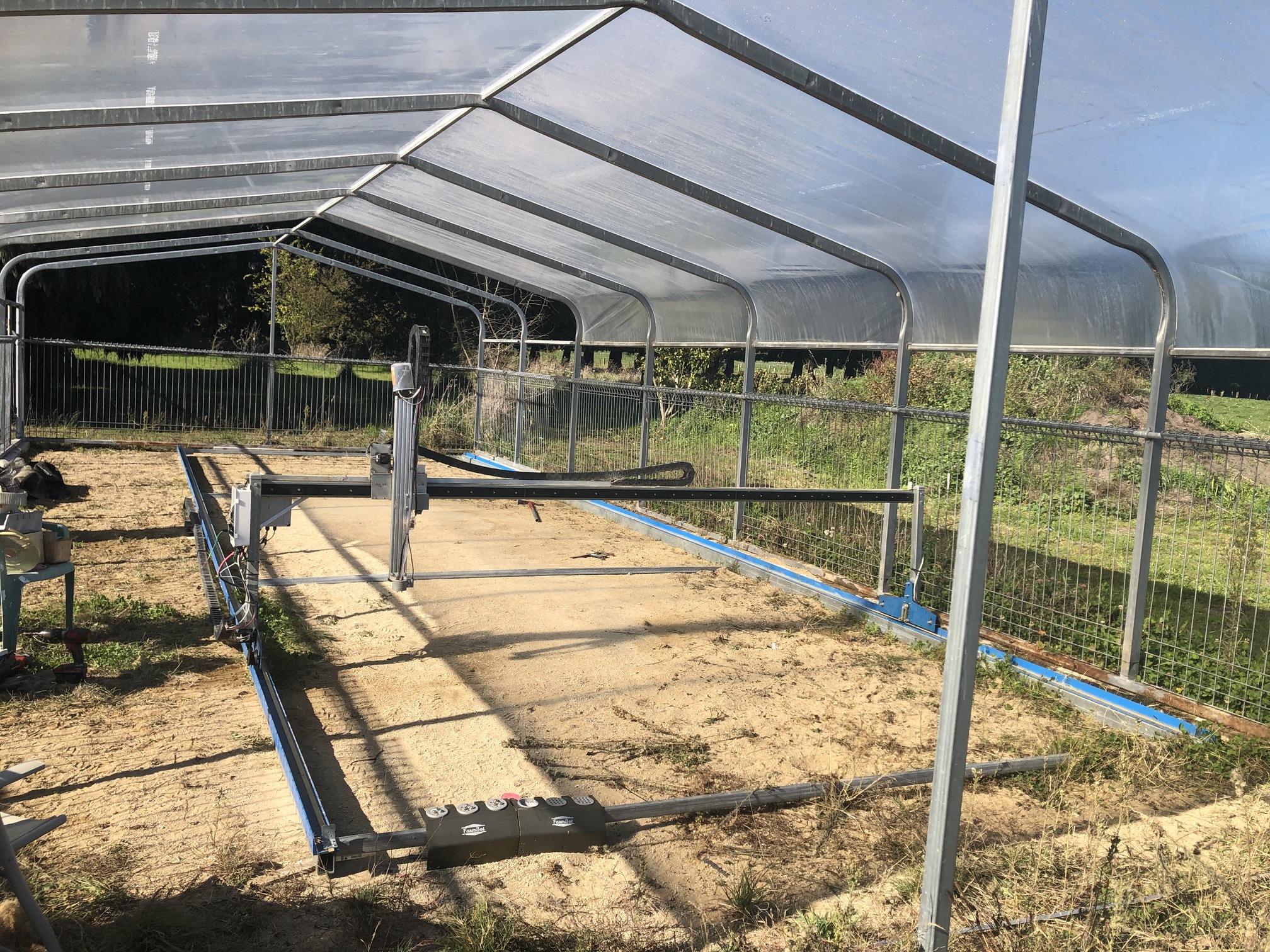
Hi i have built a 4 m x 12m farmbot xl [max]. i brought the 1.5 genius electronics and the rest of the parts local here in new zealand . i have been building cnc plasma and routers using candcnc.com controllers so i know how most of it works.
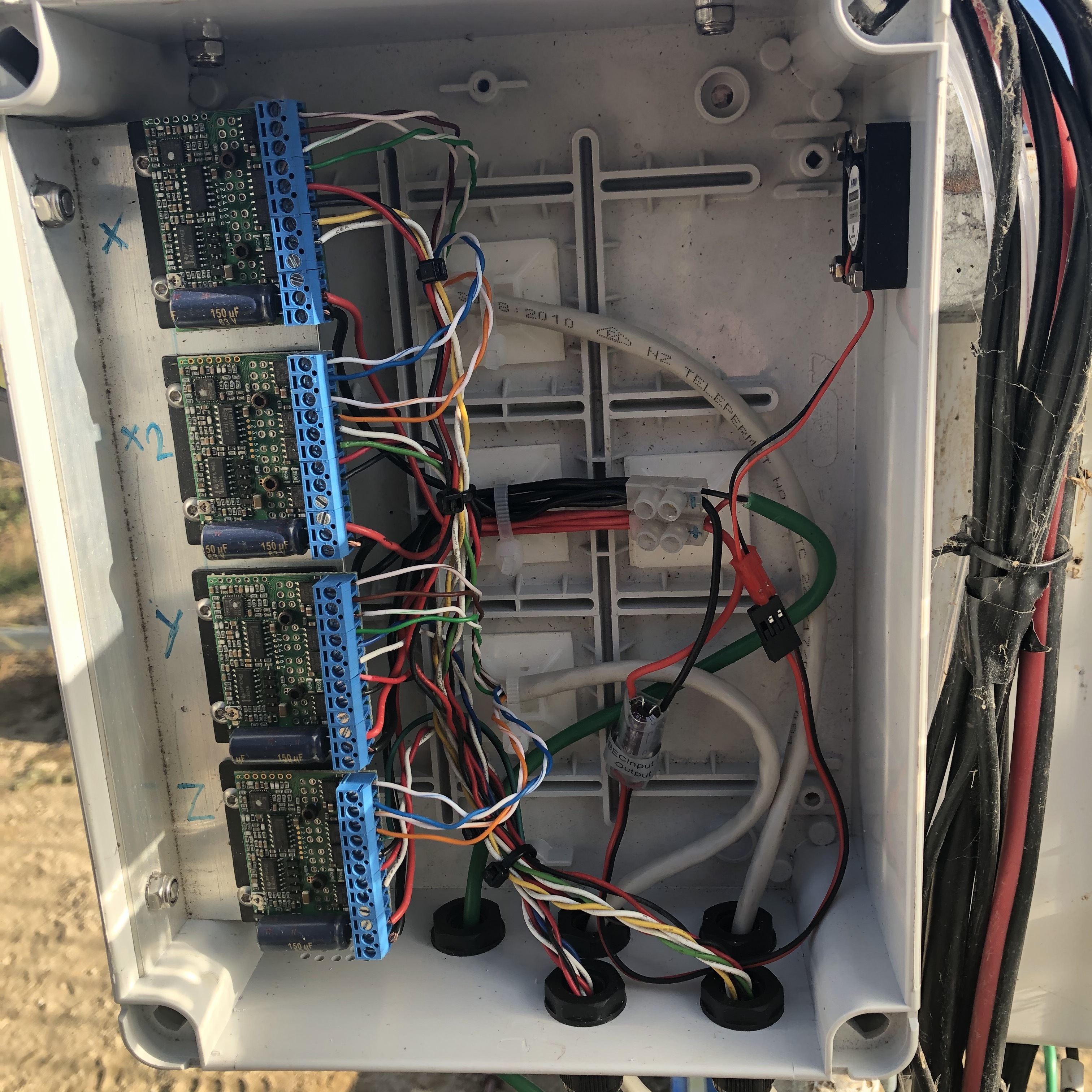
I used 23 frame motors brought larger stepper drivers but the motor did not get enough power to move . so i have just made up a extra box with 4 geckodrives in it . i have wired it up to the farmbot board with a sperate power supply cable at 24v direct to gecko drives… i have connected step and dir … the question is the other conections —
farmbot ---- gecko g251–
estop common ground
, enable disable
, gnd ,
so the question is where do they link up --estop to disable ???
gnd to common ground??
enable to ???
I would use an inverter IC to supply the Enable voltage. You could hook it up so that when the E-Stop is active, the inverter loses its “on” supply and the enable voltage is switched off. I also used to use Gecko drives on my lathe before I switched to servos :).
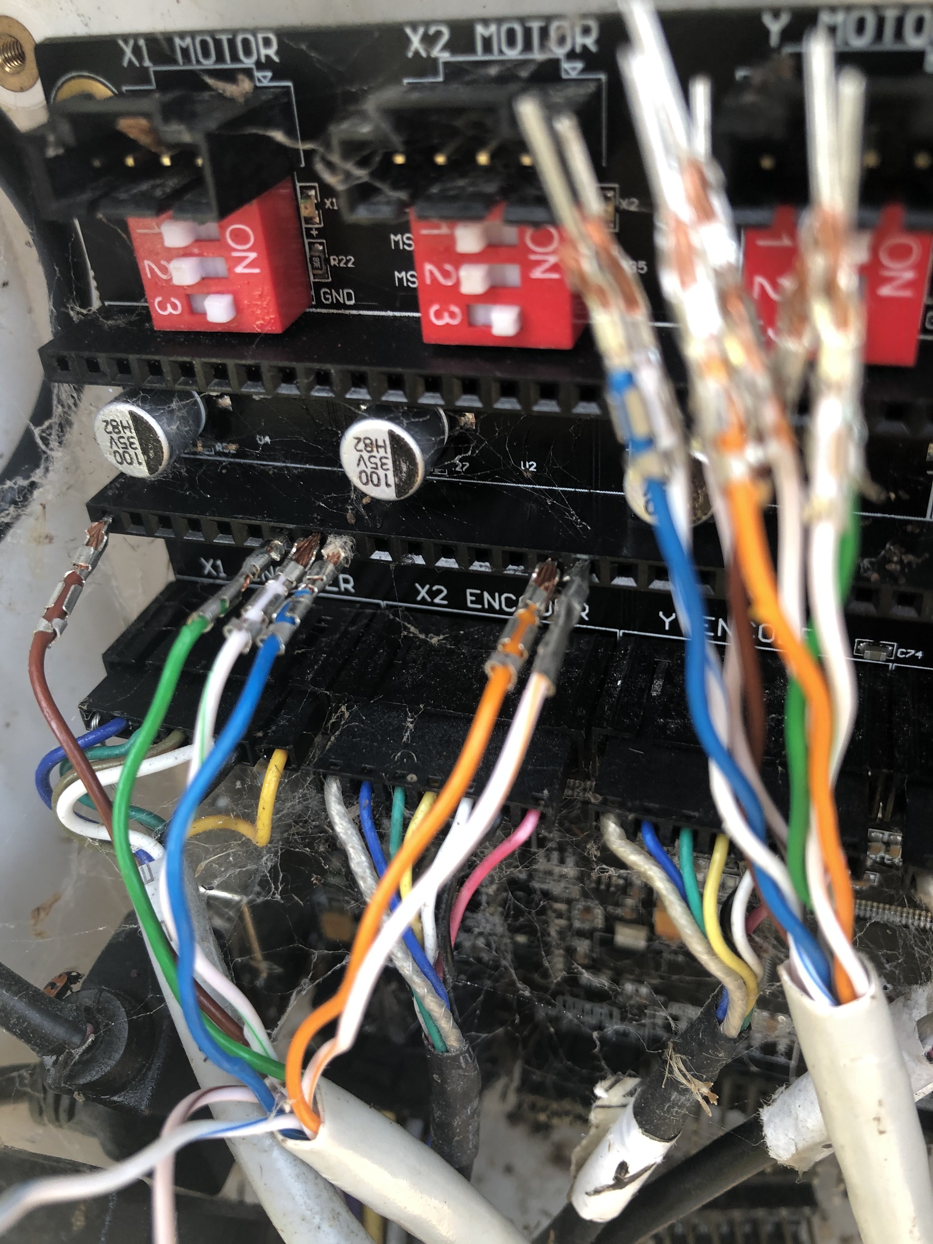
HERE IS A PICTURE BROWN IS ENABLE GREEN IS STEP AND DIR IS WHITE .
THE OTHER WIRE FROM THE GECKO IS DISABLE AND THAT WIRE COULD GO TO SLEEP OR RESET ?? NOT SURE WHAT IS THE BEST?
IN THIS PICTURE . X DRIVE OF THE GECKO DRIVE IS BROWN /WHITE IS GND AND BROWN IS DISABLE … ON THE FARMBOT BOARD I HAVE AVAILABLE I HAVE ENABLE ,RESET,AND SLEEP ??
It seems like you are on the right track, but because I haven’t done the same thing as you, I can’t offer help about the decisions that you will need to make as you go along. That being said, initially I did consider a similar path, but decided to just use the standard config and accept the size limitations for the time being.
I can’t see why you wouldn’t get the system that you propose working though.