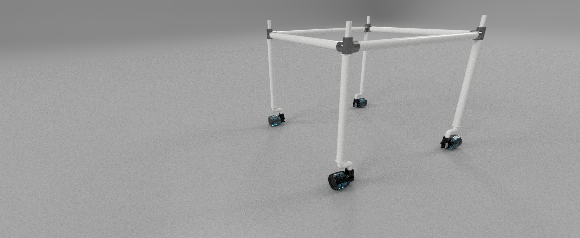
For the last month I have been working on a prototype for a drive base. This is what I have so far. I have printed 1 drive wheel and motor mount. I have test the movement around the yard. The wheels will need to be bigger for this motor type. The mounting hangs up on grass clippings. I had worm drive motors from automotive window regulators laying around so that’s what I used. I was planning on using geared motors but I did not want to buy them at this time. Geared motors will allow for a much smaller mounting as the motors would be inside the wheel. Once I find out if the frame is strong enough I will then look at purchasing these and changing the design. All feed back is welcome.
1 Like
Do not forget cross braces that structure looks to have many places it will just over time twist out of shape. Also you will notice a lot of the existing farm robots have bigger wheels this allows them to cope with someone leaving hoses or so on in their path. Some farm robots are also tracked to allow spreading weight over a larger area so causing less compaction. So I am that sure how wise small wheels are.
Also there looks to be no suspension unless there is 4 springs and shock absorber hiding in the design. Suspension would be to keep all 4 drive wheels on ground if possible so hole appears under wheel the wheel goes down into it. Again reason where small wheels get bad as well can disappear into a small hole and get trapped quite simply.
This is a interesting leg/wheel hybrid that can be done in a big wheel mounting area of course an item like this is not going to work well in your current design where you can only fit a small wheel.
2 Likes
I will agree with all the points you have stated. I have not decided on which way to suspended the frame. I have been thinking a simple equalizer beam to make the frame a three point attachment.
The wheel size is limited by my printer bed size. I would need to make them a two piece design. My other thought was to use balloon wheels. I think using ninja flex a ballon wheel could be printed.
Thank you for the feed back.
http://www.thingiverse.com/make:60267
Please don’t fail to look at tracked. There are quite a few different 3d printer ways to make tracked and manual methods.
The bike chain based tracked here is impressively strong.
Again it the same thing with tracked and using larger wheel you get to use higher mounts for motors and be able to climb over anything in your path. Something else to remember with tracked you get a bigger foot print on ground that can increase stability. Skid steering of tracked you would only require 1 motor on each side. Again this comes down to how you want bot to move. 4 independent wheels would normal suggest able to move in every direction and a total of 8 motors. Skid steering is normally straight forwards backwards with minor turning to avoid ripping up stuff. If you are driving it skid steering style serous look at tracked is required. Yes track costs a bit to make but reduced motors so reduce power usage can come into its own.
In inflated wheels do require extra maintenance. PSI in inflated wheels aligns to current Atmospheric pressure, that of course always changes. So for a low maintenance machine inflated wheels should be avoided. There is a lot of work attempting for mining and the like to get to pure air less wheels for all usages.
Do look at the legged wheel designs as well if you are purely stuck to small size wheels as these are built in pieces.

The worse problem for a robot is getting stuck somewhere.
Tracks do have advantages and disadvantages. As you stated the skidding of the track when turned is one of the reasons I chose wheels. Also the torque to turn a stationary track. The last bot you linked was very interesting! Wheels can be changed easily. If the bot is working a plot of land a different wheel would be need. If it is working a greenhouse with flat floor then maybe slightly bigger wheels would be needed. The application will determine the wheel design.
The Balloon Wheels do require more maintenance. My thought was to use the vacuum pump to fill the low pressure wheels. I was thinking of using the inflation as a way to lift the bot off the ground. Automated tire inflation is used on large tractors to add in traction in soft or muddy conditions. Also to keep the tires inflated for small air leaks. Tire pressure system
The legs of the bot rotate. The degree of rotation will be limited so the wiring does not tangle. As of now I am more concerned with the king pin. I don’t know how much defection it will have. Even the axle for the wheel has some. When it is as long as the leg it will be a lot more. One thought was to make the legs shorter and the spindle longer, adding gussets to the corners. I planning to print one and test it. Then go from there.
The way that the legs are designed will allow for this to work on a tubing track as well.
I also think the legs can work on the circular design as well. The legs can be used as the outer support and drive the radial arm. The applications for this design can be adapted to meet the needs of other projects as well. Once I am further along in the design I plan to release the files on the wiki. I still don’t have a name. I am sure it will come with time.
The track high torque to turn a stationary track is a double sided item. The high torque means when machine stops somewhere to do something it stays put as well.
We humans are not very considerate to mobile robot platforms. You fairly much bet at times hoses and small tools like plant pruning secateurs will be left in the poor machines path. So fairly much has to able to climb over 5cm/2 inches without causing self a nightmare and humans will fairly much drop the same size bits of stuff in robot path not matter if it plot or greenhouse flat floor. So decent size wheel or something like a legged wheel or a track system to deal with us Human pests. I would guess your current wheel centre point would be lower than 5cm. Bare min wheels you are looking for is 10cm diameter as conventional wheel unless you want to be making sure nothings in path.
Something else people don’t think about using low pressure or high pressure in tyres both increase wearing. So yes you see farm tractors using the Tire pressure system but the price they pay for this is accelerated wearing.
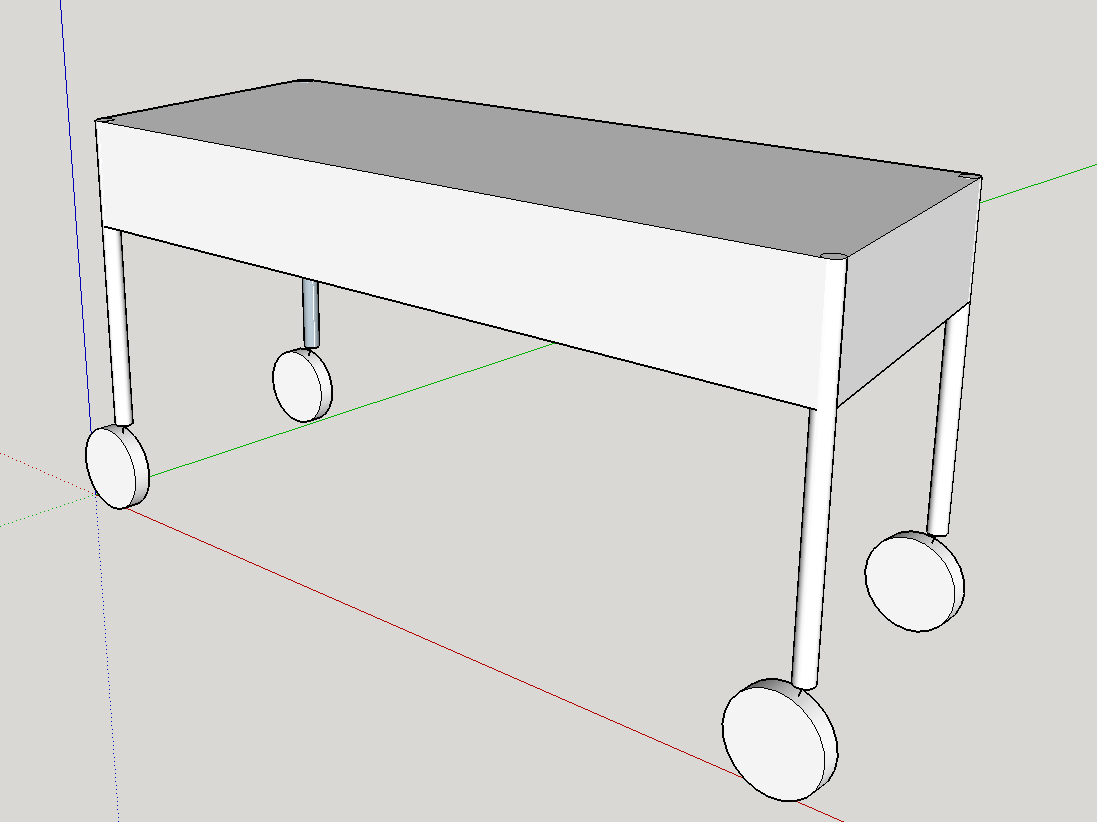
The picture is misleading. The wheels are larger then 10cm. The diameter is around 11cm.
The path you are following seems to be the one followed by others, but I’d say it is needlessly complicated. This system needs four propulsion motors and four steering motors. This does grant you a lot of flexibility, but I don’t think that outweighs the costs. My initial suggestion was going to be to connect the pairs of legs front to back, but then thought the better idea is to switch to a motorcycle and sidecar arrangement which eliminates one of the posts, drops the powered wheel down to one or at most two and only one steerable wheel. My final step was to add back another “sidecar” wheel on the other side to even out the drag.
So here is my suggestion, Start with a two wheel electric Scooter. Replace the motor with a single large stepper motor. Reconfigure the steering to be controlled with a servo. On either side of this base will be an outrigger supported by a large light bicycle wheel. If you want to work 1m wide beds separated by with .33m paths, then this system should support an overhead rail 2.33 meters long. That way the bot can work beds on both sides of the path and have the levelness of the rail be corrected by adjusting the height of the outriggers.
So diamond foot print on ground instead of T as current diagram has would have to be considered. . If going for fixed wheels steering could be skid steering put the drive motors on both of the outer edges this would be reduced mechanical complexity.
You could, but easier to power only one wheel or just the center wheels as that is where all the weight will be. If you power the outer wheels you should switch to a tricycle arrangement as it would be too hard to have solid contact on all three wheels in a row on uneven ground. Also if you did, you need two motor’s instead of just one. Maybe the better arrangement is a tricycle, but power the front wheel, as that would improve turning. I’d say do what the Farmbot people did, get the system working on the simplest hardware layout possible and solve all the other problems that come up. You can always come back and add more complexity to the hardware later. The big challenge is not to get something rolling around a garden, it is to get something actually gardening. At first that will be in nearly ideal conditions. Only later once you solve the initial problems do you worry about wheels getting stuck.
The initial issue is definitely defining exact location for a reasonable amount of money.
That is very interesting concept. I was planning on using only two steppers for steering. This would support crab steer and 90 degree movement. I just can’t seam to get past the suspension mentioned earlier. So a trike design maybe what it ends up being. If the center drive wheels were able to float up and down I could see this working. I just seen a router with cnc tracking with a camera. They used dotted stickers for tracking then overlay the profile on the material virtually on a screen. Very interesting. My first thought was the FarmBot could use somthing like this. Shaper Origin was the name of the router. Sorry to get off topic. I will keep the trike design in mind.
RichardJHauser one wheel in centre is still two motors. One for drive and one for steering. Solid contact on all three wheels is suspension design. Even in a trike because you don’t want the frame rocking between wheels as it doing things.
Skid steering for minor course correction the power difference between having steering and using skid steering is close to nothing but with massively reduced in mechanical. How often is machine turning vs complexity.
Josh trike design you do have to remember mass locations.
https://zeept.files.wordpress.com/2006/09/WindowsLiveWriter/SuspensionDesign_12DF5/image{0}[9].png
Not matter what you end up happening to look at Suspension stuff. Now if it going two beds wide having a independent head each side of the machine would allow to run a fairly much traditional moving frame suspension. Of course this means more complex programming because machine would not be a pure stable XYZ any more.
Josh the hardest thing about designing any robot/car…
- working out what you can compromise. Turning speed, Speed of motion, Mass, size…
- getting the suspension to work without it being a complete beast.
The diamond design if it skid steer I mentioned the two centre wheels are basically dumb over sized caster wheels to prevent frame falling forwards or backwards. So most of mass would be sitting on the outer two wheels. Yes two drive wheels with each drive wheel having two stabilisation caster wheels and nothing in the middle is totally possible.
The current farmbot running backwards and forwards starts adding complexity to making a mobile robot. Caster wheel stabilised skid steer does not like changing directions by 180 values.
Josh do remember not every wheel has to have drive or be 100 percent controlled in a design. Caster wheels were the wheel is left up to it own devices can be a real head ache solver when trying to keep electronics simple.
@oiaohm Correct, yes two motors. I was thinking the number of the more expensive drive motors, but you are right and realistically the steering motor may need to be pretty powerful.
Also I love that skid steering link. The ability to turn without moving laterally is very useful.
@Josh I also just watched the TESTED video on the Shaper Origin and I think it is completely on topic as that is one way of getting positioning, but I don’t think that is the best way to get positioning.
The options seem to be:
- DGPS - but that doesn’t seem accurate enough (10cm per Wikipedia)
- Inertial - probably not accurate enough, though probably would be if used in combination with other system
- Some kid of multiple laser/sonic range finding system triangulating distance from robot and passive beacons
- An audio analog of GPS using active beacons http://cslab1.bc.edu/~csacademics/pdf/14Valeri.pdf
- An optical positioning system like the Shaper Origin using fiducial markers or IR beacons to triangulate by angular position of beacons.
Of the group I like the sonic GPS idea. The beacons would be a solar panel/battery, a speaker and a triggering system. I think the easiest trigger is something like a bluetooth or wifi connection to the robot but it could be a different kind of sensor or an accurate clock. I expect that you’d also need some kind of microphone on some of the beacons to adjust for changes in pressure which would affect the speed of sound. I would expect this could be reasonably cheap and very accurate if you had multiple beacons and we could guarantee beacon immobility. I think it would work even if there were trees or other obstacles inside the area. Also it would be easy to add in a second positioning sensor for error correction and to get rotational positioning of the robot.
I even found a company that has something like this:
http://www.hexamite.com/
One reason I chose the quad drive with a modified syncrodrive was to be able to position the bot accurately. I was not planning on using the drive wheels to take the place of the current FarmBot y axis. I was still planning on using the CNC frame to perform the operations. The drive base was going to only be used to move from one bed to another.
Now if we design a platform that can perform the operations in place of the y axis we are moving closer to present university test agriculture robots. If this is what we are going for then we need a different navigation something more like GPS with RTK. If we are just working our gardens then I do like the idea of using Triangulation Beacons. This was what I wanted to do when I started out several months ago but could not find any information for this type of system. Thank you for the links.
If we are able to locate the bot the design could be different. For example a robotic 6DOF arm could be used to harvest. This is not something that will happen over night but maybe in 2-3 years we could pick our first fruits.
I like the tricycle design because it does not need suspension. Three points of contact with low center of gravity. The design is simple and easy to build. I am worried that one drive wheel will not work well. Traction is key for any off road vehicle. So tracks or all wheel drive are the only two option in my opinion.
I am going to move forward with the design I have presently. I will be changing the frame somewhat. But this will give me a drive base to work with the navigation. I think the navigation is the key to any system like this. The physical frame can be modified at anytime. The firmware should be modifiable to meet the needs of other platforms. One just needs to start and keep plugging away at it. As I progress I will update this thread. Thank you for all the great feed back it has been a great help. It will keep me from getting headaches when the bloody thing is not working the way I thought it would.
1 Like
http://www.robotplatform.com/knowledge/Classification_of_Robots/wheel_control_theory.html
When looking around came across a site listing all kinds of different drive train setups.
Josh above is a solar passively articulated robot 4 wheels and 4 motors and a pivot point can be done with 2 but reverse is harder(think trailer reversing do you want to program robot todo that or would you just like to swap driver from one side to the other). Yes fitting a pivot point in the mid area somewhere in a 4 wheel design provides a lot of natural suspension solve.
It is possible to design a frame that is articulated and skid steering in one by including means to solenoid to lock the front and back of frame straight and while frame is locked straight skid steering methods can be used when unlocked Articulated used. Yes you can leave the left to right up down pivot unlocked to keep wheels on ground.
Skid steering is always a price on wheels and power usage. Articulated Passive bigger turning circle than Skid steering but tighter turning cycle than Skid steering ideal turning circle for min tyre wearing while achieving min tyre wear.
Everything is a trade off design these things Josh. Wheels don’t float over soil but create compaction. Wheels in rails on beds would have to considered. Rails under wheels can provide equal compaction to machine being on tracks also after machine finds area keep it aligned.
The least amount of motors that can drive over a bed with least tyre wear I can come up with is 2 motor front wheel drive passive articulated robot with 4 wheels. I would not like designing the control code to have it reverse. Advantage over just a trike is no centre wheel disadvantage over trike not able to turn as tight.
Turning circle vs power-usage vs mechanical complexity vs programming complexity. No matter what you choose you have to lose on at least one of them.
@Josh My apologies, I completely misunderstood the scale you were proposing. So your idea is a mobile platform that moves the existing Farmbot structure. That is very interesting as it changes the whole dynamic of location and could allow the system to optically or physically lock on just two pins. The challenge then is to create a frame that is stiff enough without diagonal braces which would limit mobility. Wow, that may be a much better idea.
So basically, you have a standard Farmbot on a mobile frame. Each time the frame moves you would start by having the system search for and lock on a pair of location pins then use them as guides to physically correct the frame location or to create location correction factors for the location axis. If the drive wheels were offset like castors then turning of the castors could allow for fine tuning of the frame location. Wow, yeah that is a better system.
So you’d need four heavy verticals, like maybe 2" steel pipe. Make them over long so all the diagonal bracing is done above the plant height. Then four largish flotation pneumatic castors. Something like: http://www.globalindustrial.com/p/material-handling/casters/wheels/10-swivel-caster-pneumatic?infoParam.campaignId=T9F&gclid=Cj0KEQjw0rm-BRCn85bm8uS-zK0BEiQAHo4vrOyfiHpY1VXiV9msmlIgYZgnrwYRH6zwmaEYb8acQGwaAkEo8P8HAQ. You’d then have to add in a drive, steering and braking/locking system for each. Locking as you don’t want the system moving once you have it positioned. Adjusting the tire pressures sounds interesting for height adjustment, but that will have some bounce and may allow some tilting with weight shift, so I’d probably just have a mechanical leveling system at the top. Way easier than trying to pipe all the castors for rotating air lines and then you can just leave the tires fully inflated.
PS I found a seemingly purchasable sonic GPS system called Cricket. http://www.memsic.com/wireless-sensor-networks/MCS-KIT410CA, but physical location pins would be much better and more accurate.
1 Like
You could have the moble bot slide into guided railings that start out wide with some slop and funnel down to a precise rail and then lock (kind of) into place for the duration of the work ni that plot. It could have its own power and water hook ups at each plot so you dont have to haul them around.
If you can lock into each plot then you could have a function where once locked it reads a pin to confirm which plot it is at. That might simplify and reduce some processing power (?) b/c it would not have to keep the whole garden loaded at once. If that would be an issue, it may not be.
For locking in I was thinking of a spring loaded lever that locks it in and then releases either on command of a actuator or just pushing against one.
1 Like
The pipes I will be using are 2" Or 60mm PVC. I chose pvc for cost and it is easy to work with. I will be using sch40 pipe this seams to have enough rigidity for the application. The axles I have designed are also PVC. The worm gear motors are self locking but there is an issue with backlash that I will need to address. This is a DIYers dream bot. I have not had time to work on it the last two weeks as school has started. That means coaching robotics started. This will take a lot of my time for the next mouth until the kids get into the grove of things. Then I will be able to keep designing. I want to have a working prototype done by February. Depending on what the kids have me building for there robotics will determine how much my printer is free.
@Josh Best of luck, I think window motors should have enough torque, but I’d be a little worried about ground clearance issues with that layout. Can you mount a larger wheel? How tall are the legs going to be? PVC should be fine, and best to get it setup and you can always tweak it if necessary later.