Sharing progress on the FarmBot prototype in Santa Fe, Argentina

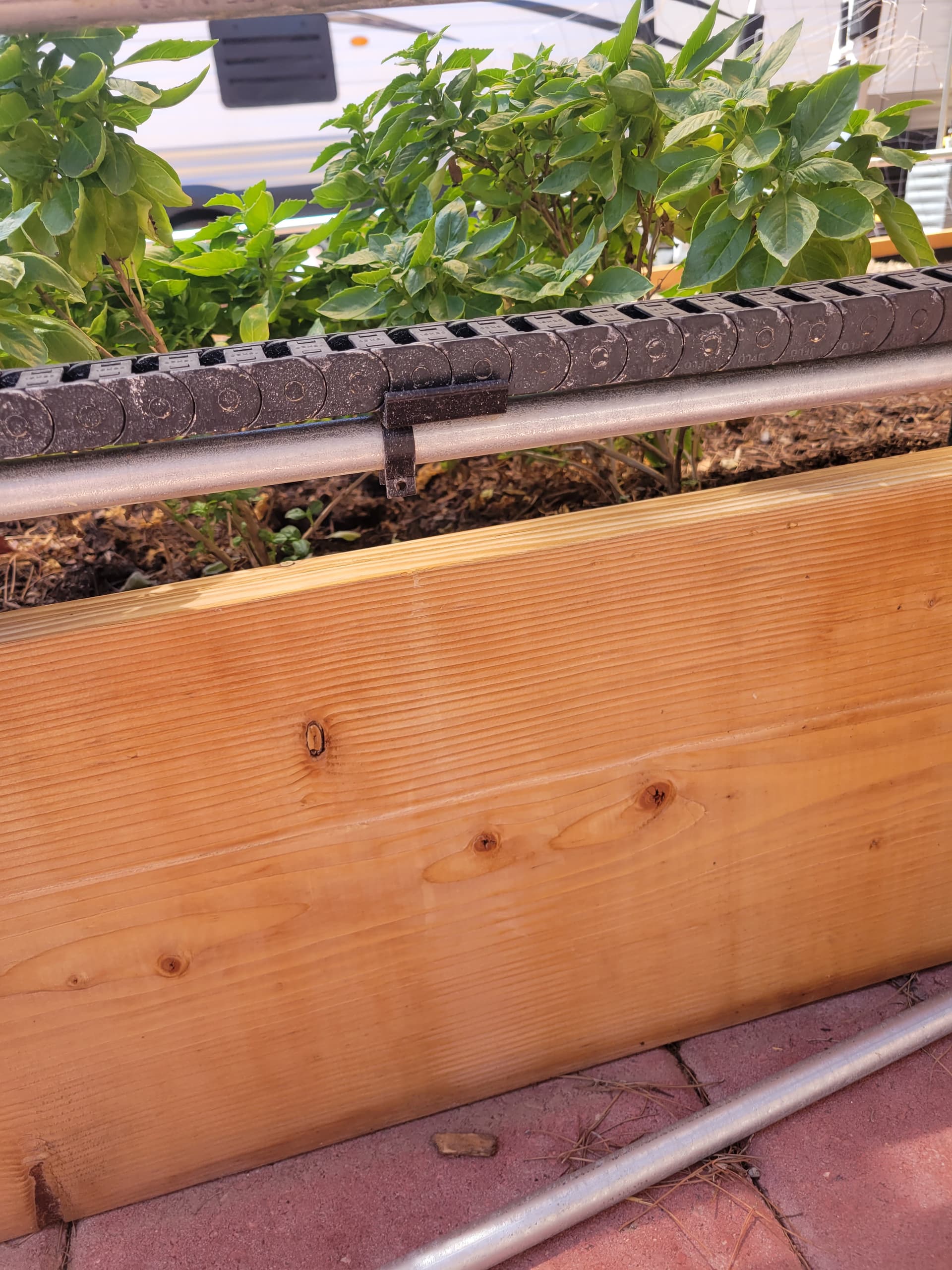
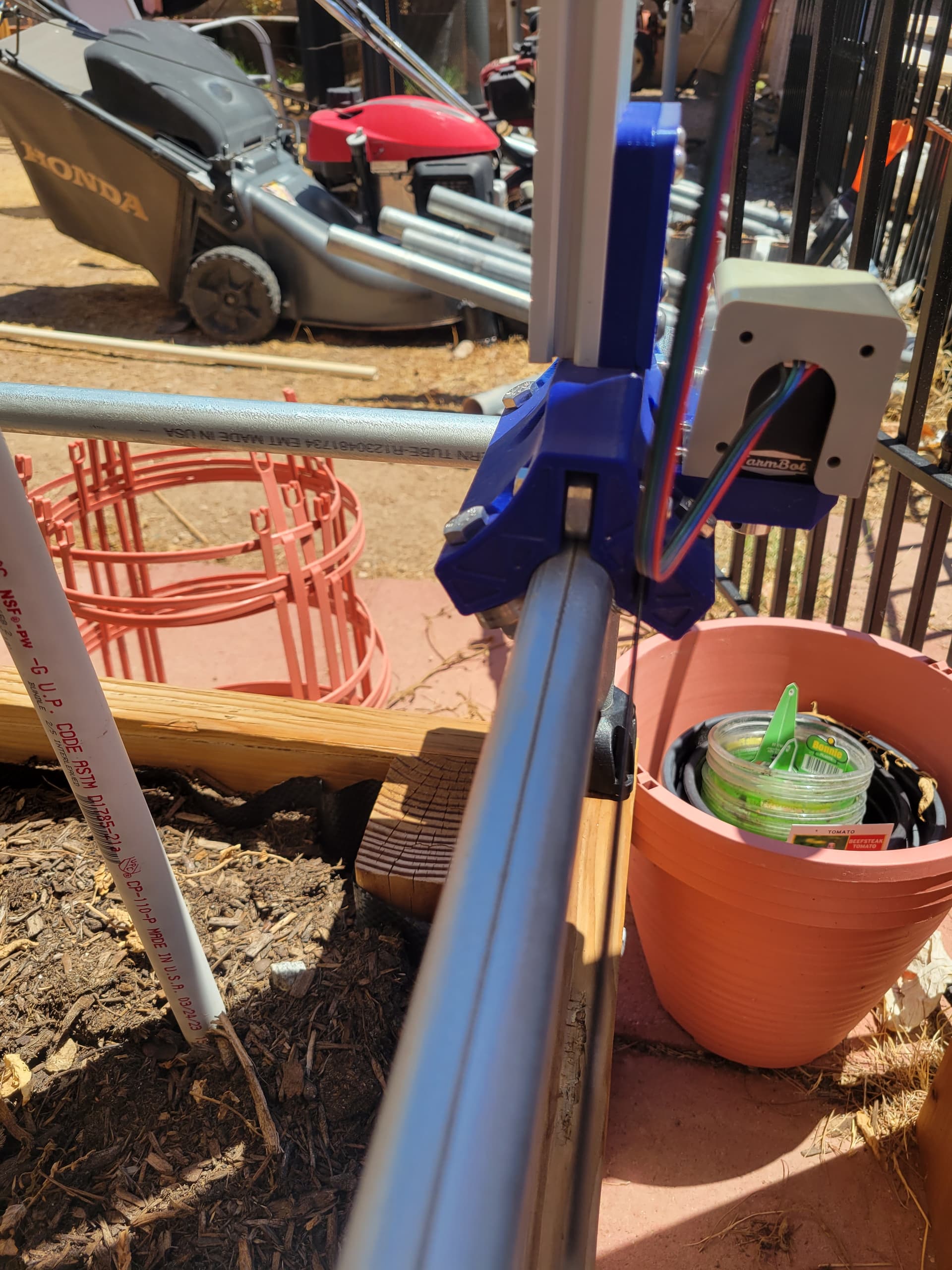
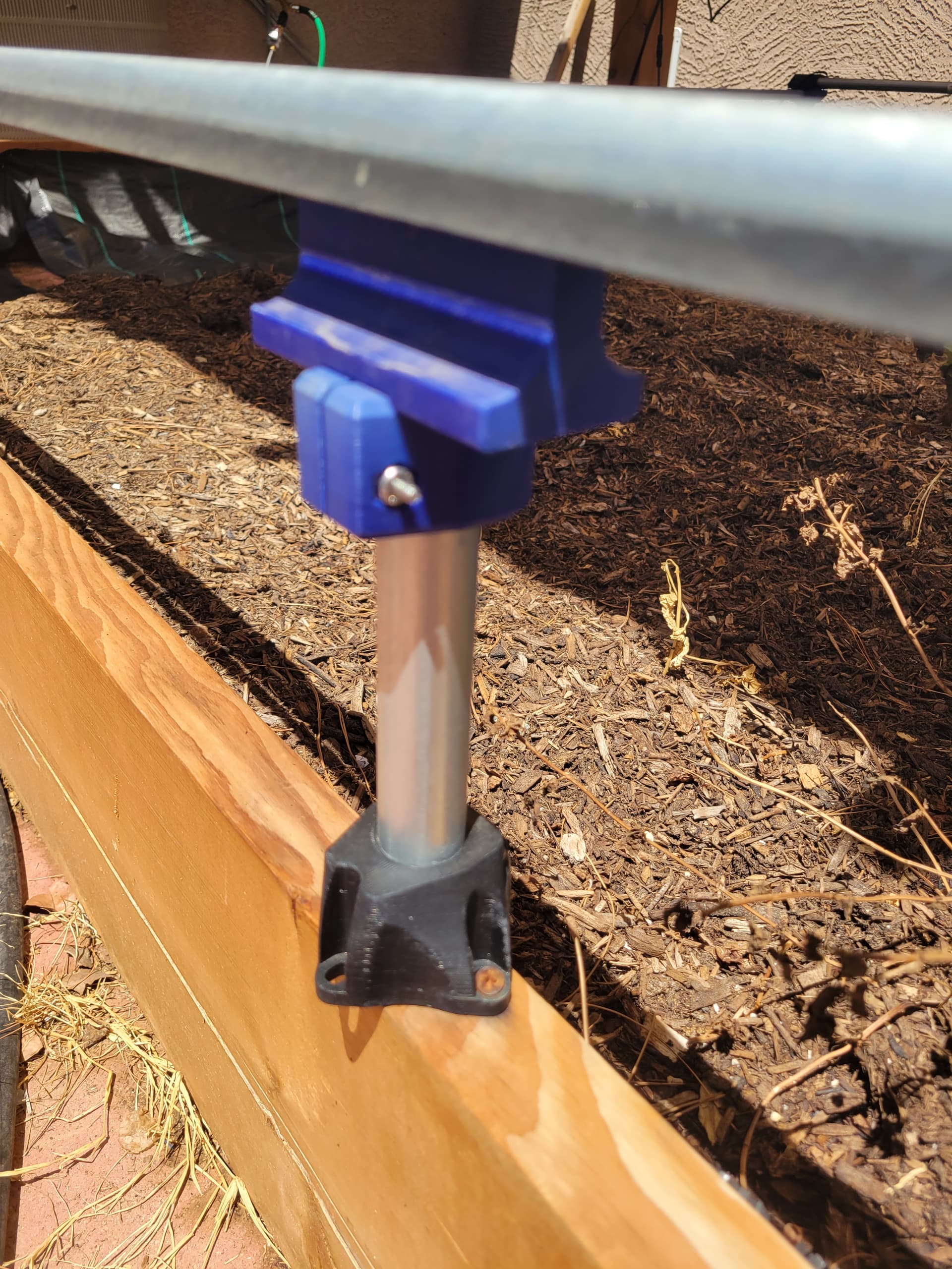
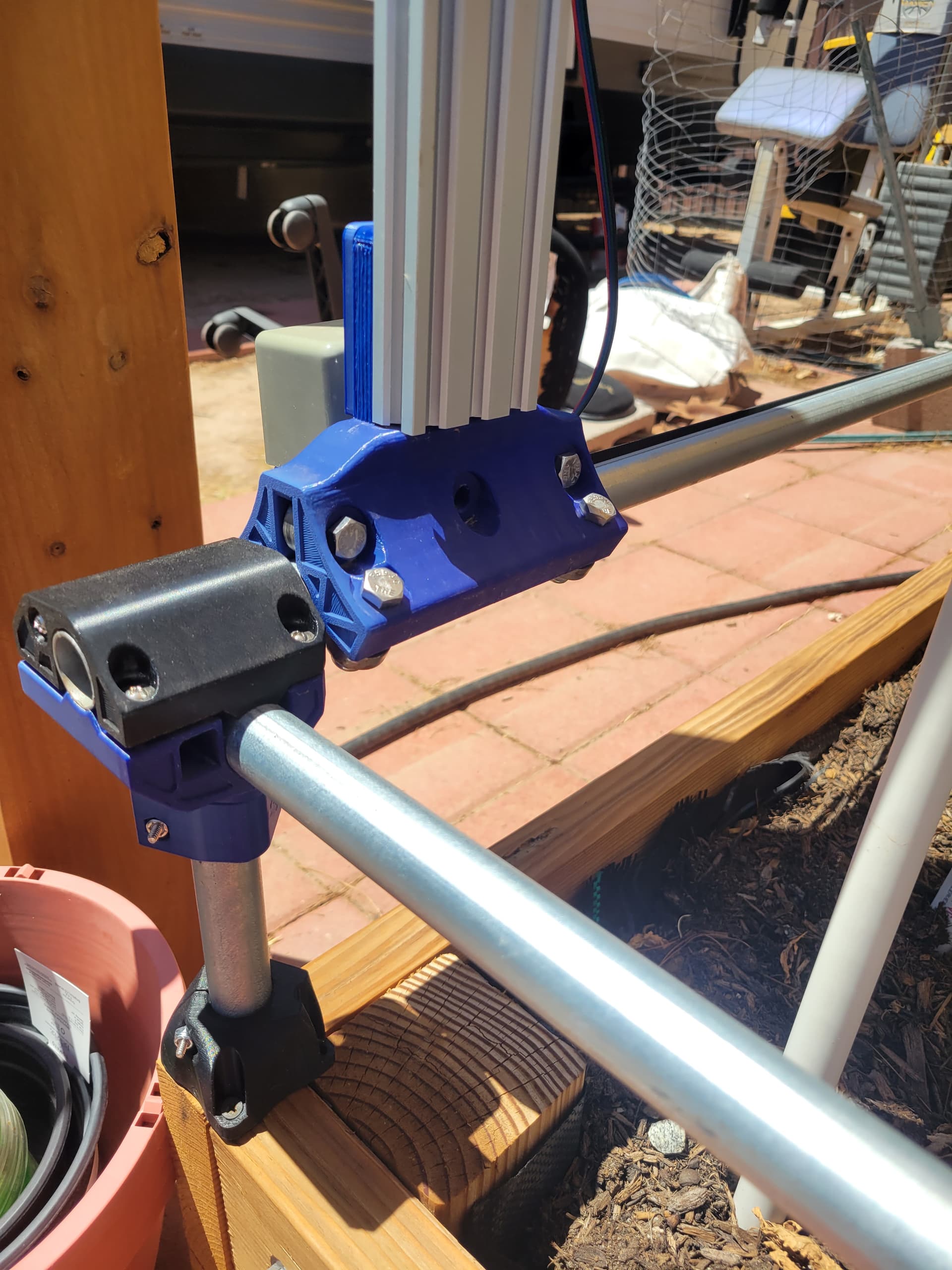
Hello community, I’m writing here again! This time to share with you the progress we are making on the FarmBot prototype. We could say that in this state it is called FarmBox! :grinning:


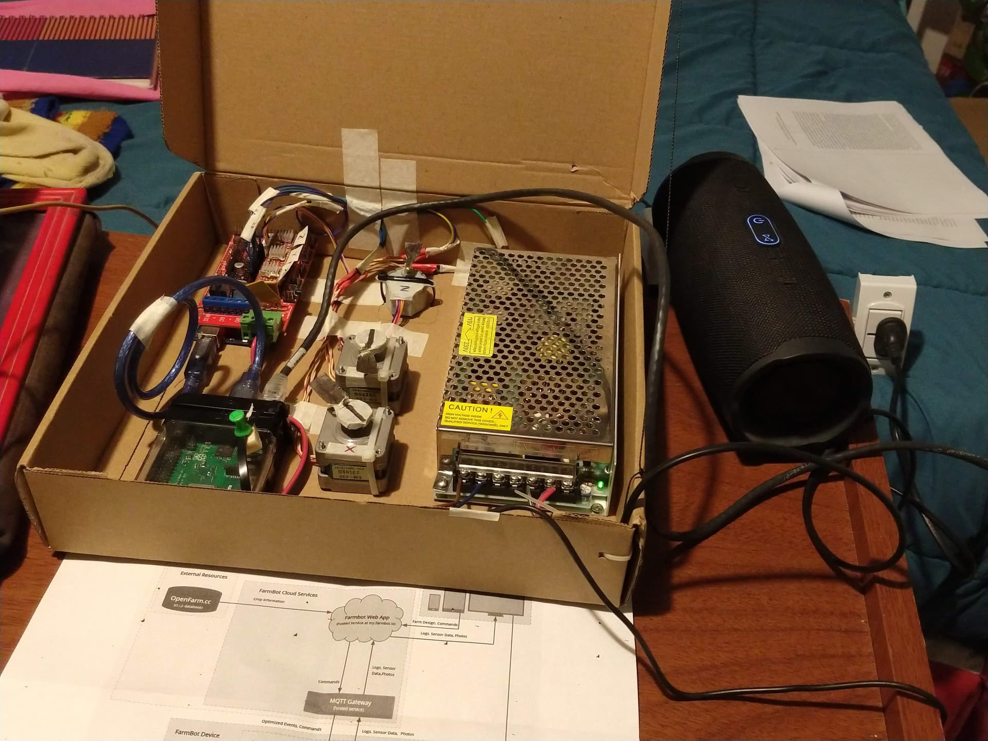
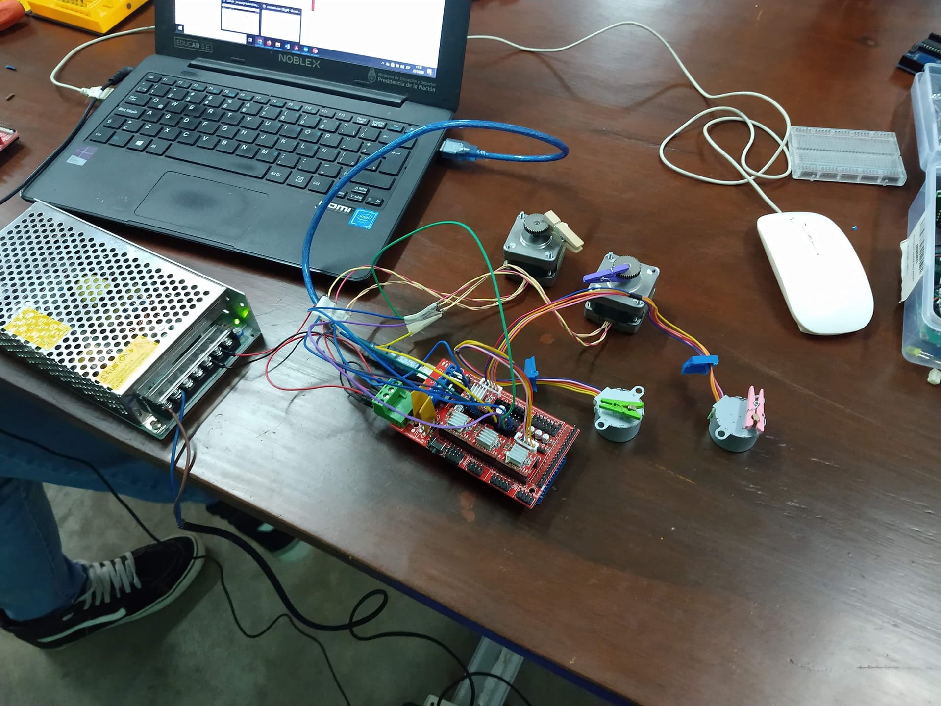
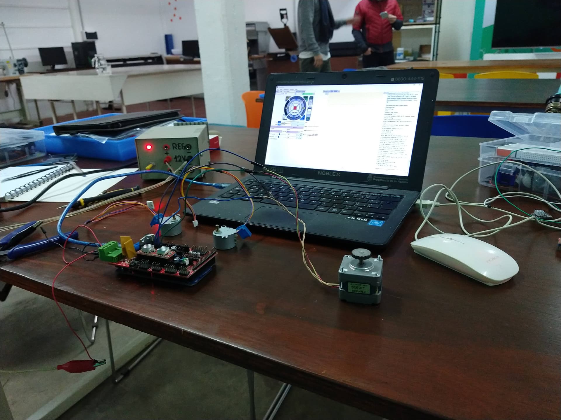
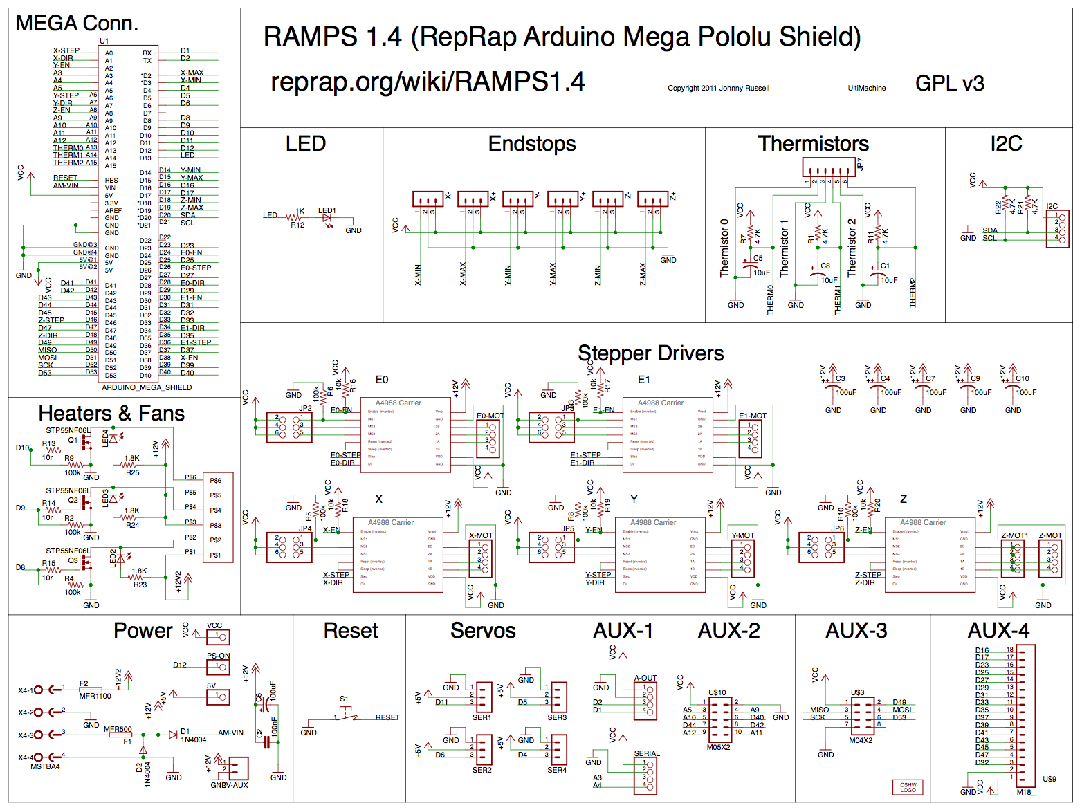
For now we have successfully working the communication of the web interface with the electronics of the prototype, based on the initial configuration of Arduino Mega with RAMPS 1.4.

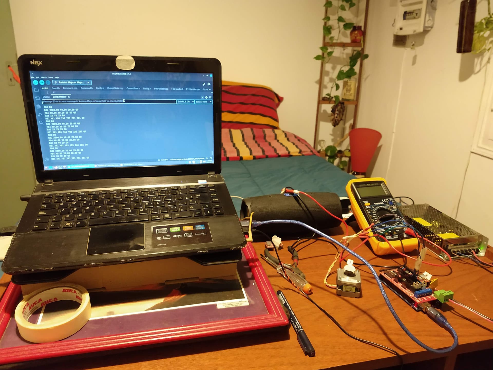
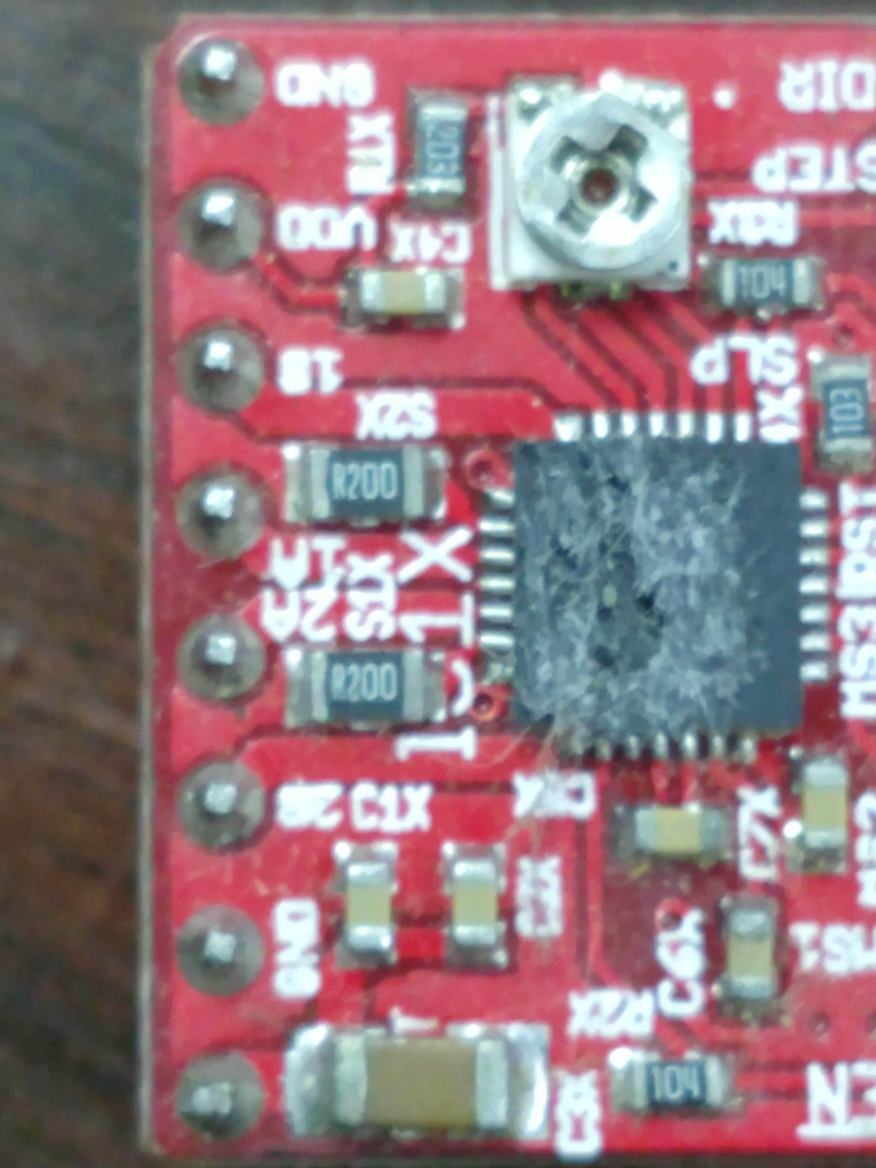
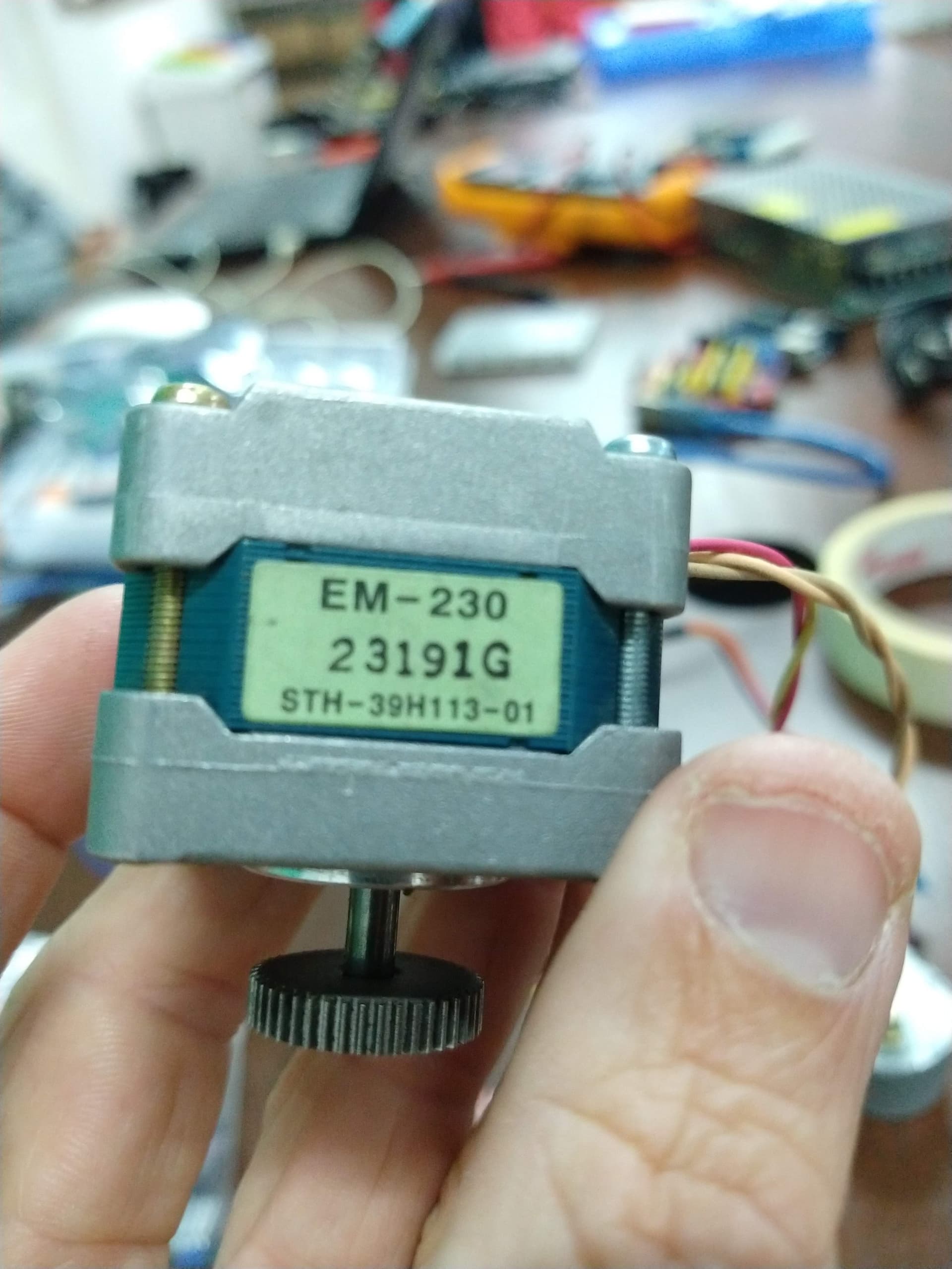
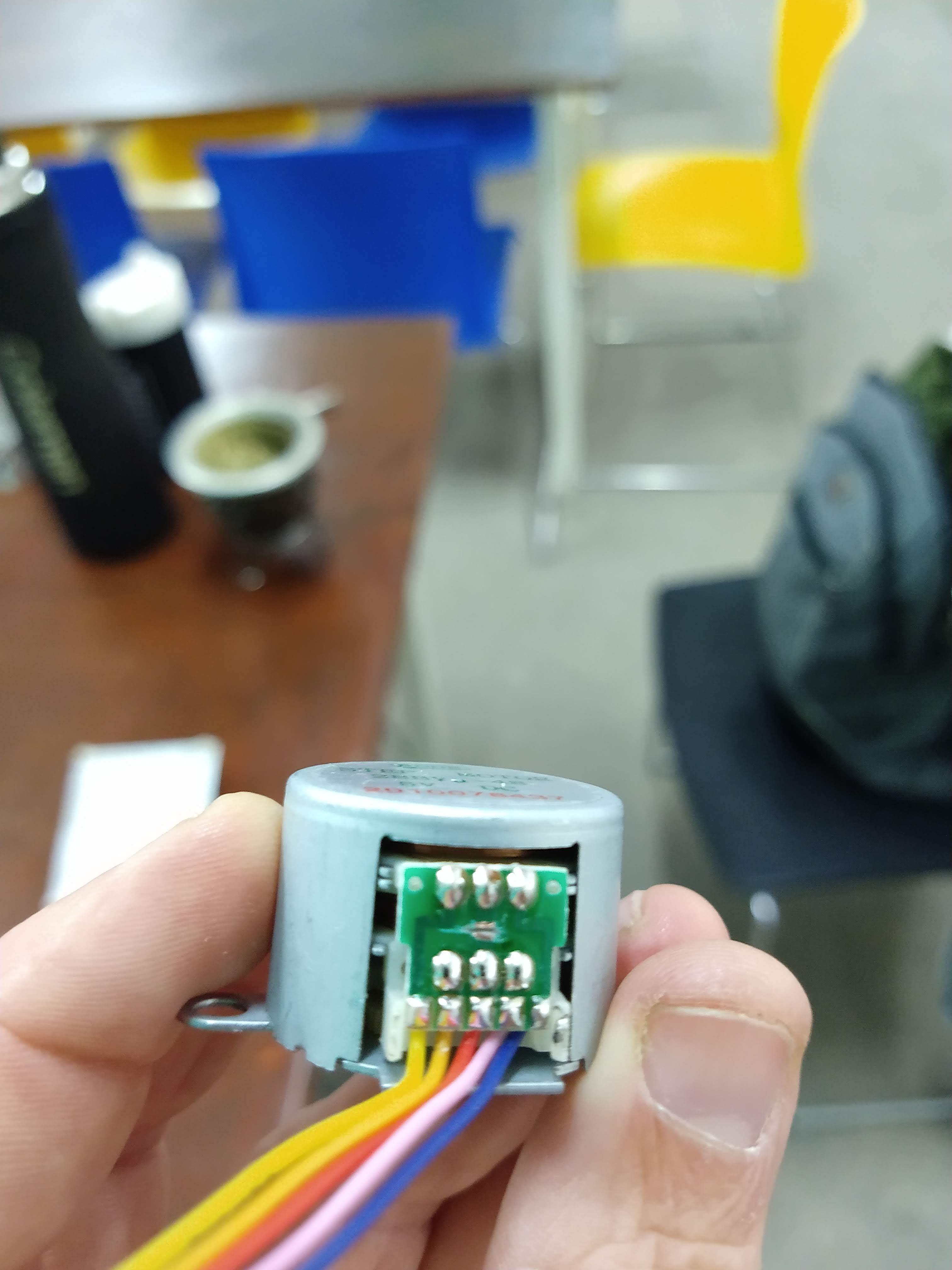
We use 2 recycled NEMA 14 style stepper motors (I think from an epson printer) and a traditional unipolar stepper motor (28BYJ-48) from the arduino kit. All the motors use an A4988 driver.

These last tests were carried out with firmware 6.6.21 and farmOS 15.4.3 on a RaspBerry PI 3b+.

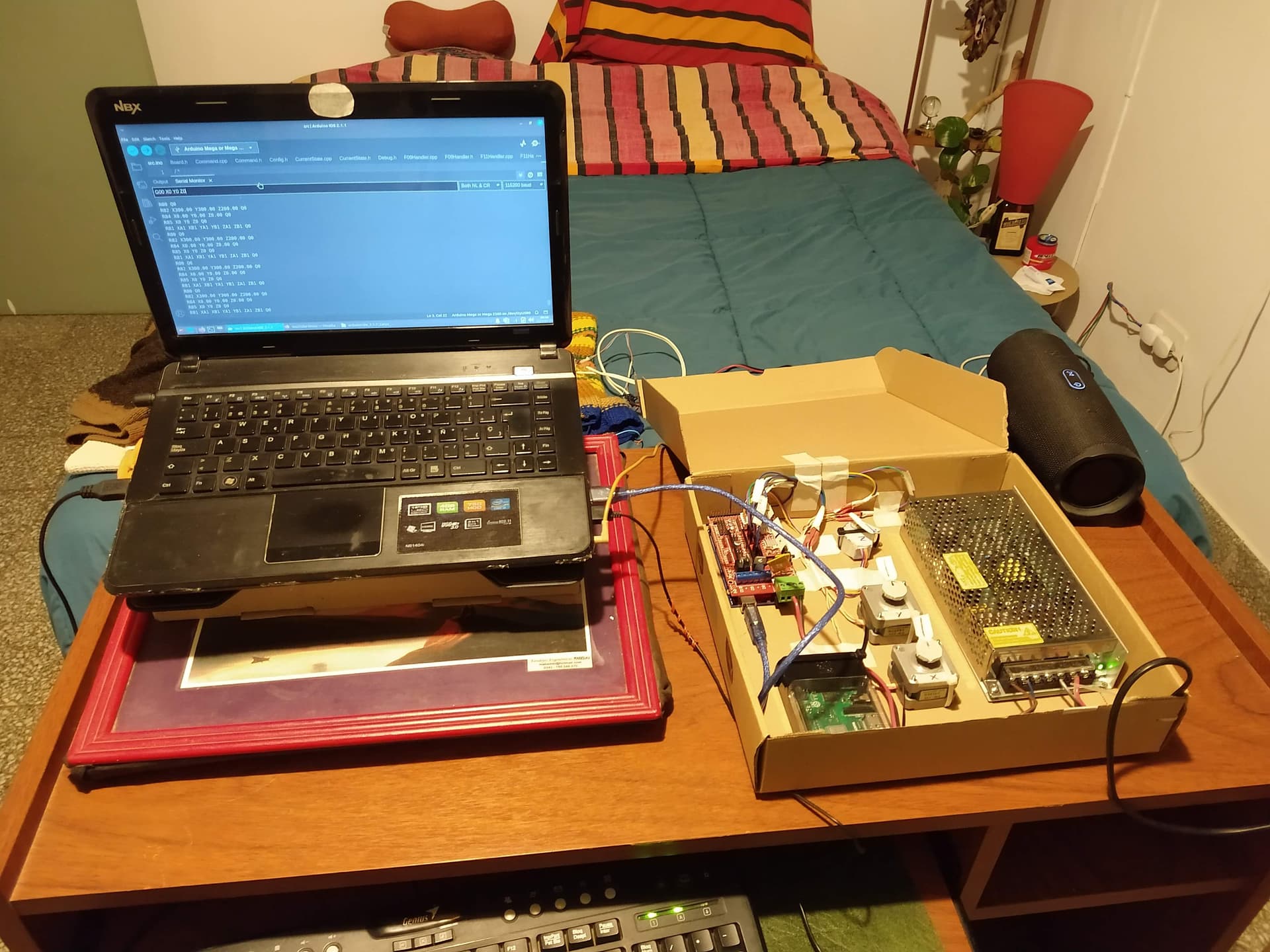
After overcoming several challenges we managed to communicate directly with the firmware and control the movement of the motors through the console, which helped us to learn more about the G and F code protocol, as well as continuing to learn about the entire ecosystem.

Video final:


Video G and F codes:

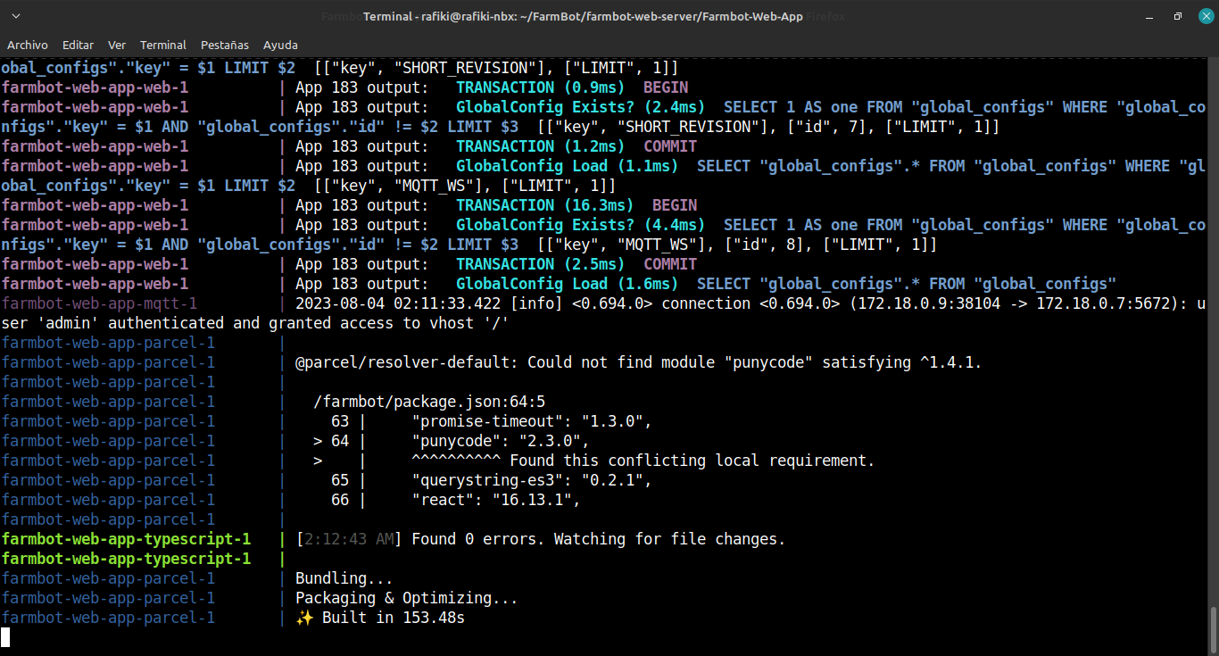
Then we were able to complete the final step (which initially gave us problems) to be able to control the electronics directly from the web interface!
We are very happy with this progress.
Thanks to the support of the mentoring at Active Capital and the FabLab programme that helped us a lot with the electronics.

We plan to publish more details of the process we are going through.
I send you a big hug and thank the FarmBot team for continuing to bet on making this project grow together with the whole community of enthusiasts, educators, DIY, and users who are excited (enthusiastic for the common mortals) with ideas like these.
:seedling: :herb: :hugs:


Español:

Hola comunidad. ¡Vuelvo a escribir por aquí! esta vez para compartirles los avances que estamos teniendo en el prototipo FarmBot. Podríamos decir que en este estado se hace llamar FarmBox!

Por ahora tenemos funcionando satisfactoriamente la comunicación de la interfaz web con la electrónica del prototipo, basada en la configuración inicial de arduino mega con ramps 1.4

Utilizamos 2 motores paso a paso estilo NEMA 14 reciclados (creo que de una impresora epson) y un motor paso a paso unipolar tradicional (28BYJ-48) de los kit de arduino. Todos los motores utilizan un driver A4988.

Estas últimas pruebas las realizamos con el firmware 6.6.21 y el farmOS 15.4.3 sobre una RaspBerry PI 3b+

Luego de superar varios retos logramos comunicarnos directamente con el firmware y controlar el movimiento de los motores a través de la consola, lo que nos sirvió para ir conociendo más el protocolo de códigos G y F, además de seguir aprendiendo sobre el ecosistema completo.
Luego pudimos completar el paso final (que un inicio nos dio problemas) para poder controlar la electrónica directamente desde la interfaz web!
Estamos muy contentos con estos avances.
Gracias al apoyo de la mentoría en Capital Activa y el programa FabLab que nos ayudó mucho con la parte electrónica.
Tenemos planeado publicar más detalles del proceso que venimos realiza

Les mando un fuerte abrazo y agradezco al equipo de FarmBot por seguir apostando a hacer crecer este proyecto junto a toda la comunidad de entusiastas, educadores, DIY, y usuarios copados (entusiasmados para el común de los mortales) con ideas como estas.

3 Likes

Hi, just few notes: Do not forget that electronics is the easiest and cheapest part. The raised bed is more difficult, rails and gantry bit more expansive and wiring + outdoor proved stuff like stainless parts (screws, eccentric support or bearings and even cables - UV protected+motion friendly) are not easy to pay and get. The really difficult part are the cable chains - expansive and should be reliable. I did print most of the parts including the cable chains. And last note, RAMS is good start but neighbors will not like the noise - the farmduino has acoustic compensated motor drivers. I did solder it manually and I have few spare PCBs if you are interrested. Good luck.

1 Like

Hi Jan! thank you for your notes. Where are you writing to me from? As far as I can see, you have done the construction on your own already.
I understand that it’s a very simple thing to do with electronics and software. However, it’s a giant step forward so I’m very happy :smile: . The challenge continues! :muscle:
I take this opportunity to ask if you used the 3D designs of the e-chain® published? if you used any other design that was useful to you, could you share it?

On another note, I’ve heard about the benefits of Farmduino compared to the initial Arduino+RAMPS setup. The idea is a first scale prototype, I think it will be 1000 x 500 mm. The proposed challenge is that the development can be done with local production and labour (in most of the parts that allow it).
I am interested to know more about the development of those PCBs for acoustic compensation that you tested. I have seen some information about it before, but have not yet reached the stage where it is needed.
Any information you have to share about your experience would be very welcome.
Thanks again! hugs :hugs:

1 Like

UPDATE

We were able to move forward in setting up the ecosystem for ofline to work. Now we have the web server version set up in a local environment, all connected by cable with a router (thanks to the internet provider not remembering to remove the router several months ago, now it was a great help to have it :recycle: ).
The whole ecosystem set up for test connected 100% with FarmBox :wink:

1 Like

Good luck on your system. I live in Arizona where we have had temperatures hitting 118-119 degrees farenheit the last couple weeks. My 3d printed parts for modifications were all printed using ASA Filament (Flash Forge Brand on Amazon). I have had no issues with the ASA in the high temperatures. Although I have had many plants burn up in the heat :slight_smile:
I personally have not printed the published e-chains but I have used the published designs to download and modify components. My farmbot is currently running on 3/4" EMT rails for the X Axis which I found to be much more stable then running directly on the raised bed. My FarmBot started as an ExpressXL. I have made several modifications and plan to make several more. I absolutely love the FarmBot and the creativity it spawns.

I Hope this helps as you work through your designs.

Thanks,
Roark

2 Likes

Hi @Roarkperry, Thank you very much for your response and encouragement!
Those are pretty high temperature levels! Already we are being shown with increasing emphasis the ecosystem problems we have to deal with. Here in Santa Fe, Argentina, we tend to have hot summers, rarely experiencing similar temperatures. Now that we are in the last stretch of winter, we have temperatures of 24°C, which is crazy for these times!
Thanks for the data on your development, it is valuable and very welcome information. Do you have a photo repository to share? pictures are often inspirational and bring clarity!

Best regards!

1 Like


Here are a few pictures of printed modifications.
Currently the top half with the Y-axis is unmodified and just rides a bit higher. I can easily raise the conduits to accommodate taller plants. But that will increase the distance from the soil and render the seeding functions useless.

Thanks,
Roark

3 Likes

Wooww! thank you very much @Roarkperry!
I’m going to let my imagination run wild and say that it could be 4 height adjustable columns with pneumatic mechanism synchronized to raise and lower the portico when it is necessary to plant or make soil measurements :slight_smile:

Back to the ground. It is very interesting the mechanism of the cylindrical rails with a real case in which to know the user experience. I understand that in this case your model is 6 meters long?

Best regards!

My thoughts where to change the mechanism of the Z-axis to be expanding height via gears. but I havent gotten to it yet. As for the cylyndrical rails, it works great but I do have supports. I am not running it the full 6 meters. My bed is currently only about 3 meters with one support in the middle.

1 Like

I understand! good luck with that when the time comes to test it.
Just thinking about height, this morning while I was in the waiting room for a medical appointment, I was thinking about this idea of another adaptation to allow automatic irrigation and sensor measurements such as soil moisture or ph one or more complementary growing beds. Thinking of a raised bed/bench with holes (on the sides or at the bottom) that allow points (Cartesian coordinates within the design of the garden) for irrigation. In addition, one could think of a type of adaptation point (plug and play) where the UTM is positioned to take readings from another sensor located in the complementary beds or in the soil itself. Thinking of servomotors that could be activated by contacting the arm (Z-axis) of the UTM with this plug and play adapter. Allowing to give current to something like a servomotor (or other mechanism) and having a sensor data reading channel.

I drew at the time a very quick sketch of what I had in mind.
Maybe it will be of inspiration at some point.

In the image there is only the irrigation channel and no reference to the sensing channel. But I hope the idea is understood at least a little. Since the English translation can’t be very clear either, I hope you can understand.

2 Likes

Definitely an interesting concept being able to water and monitor a secondary bed. I will have to give it some thought as well

1 Like

Hi … please help … I’m goint to mount my farmbit using ramps 1.6. I’m want to know how you simulate … and how can I’m endstops instead expanse steppermotor with encoder attached.

Hello @willian.virgilio! how are you?
I think that what I can help you with is indicating where some of the information that I have found is, I think that with the current documentation there is everything necessary, leaving aside what is related to making the Arduino + Ramps + Drivers + Motors electronic set work. (On that there are many resources on the web, anyway I share some of those that were useful to me)

First you can test everything without using limit switches and encoders. Without that everything can work the same. Once everything works, you can continue exploring how to configure the limit switches using the jumpers on the ramps and simulate it with some basic switches or just with two cables that join and separate :smile:

You can share your path with us, I will try to help as much as I can.

Good luck!
a hug

Thanks @luciano.dlf … that will help me a lot… i’m mouting my farmbot… if you have a documentation how to install the endstops will be very helpfull too…


3 Likes

Good job!.
Thanks for sharing. Did you buy the parts separately from FarmBot or other local suppliers? Or did you buy the express kit without Farmduino?
I haven’t done anything about the endstops yet, we are in the process of acquiring financing and materials to make a scale model where we will integrate what we have already advanced on the electronics prototype. At that time we will include limit switches (endstops) first and then encoders.

I invite you to share your experience when you solve it.

As I understand from the documentation that I have already read, the pins of the ramps where the limit switches are connected are used, these pins must match the configuration between firmware (arduino) and farmbotOS (raspberry), I think the latter can be configured from the web interface. When the switches are activated (a bridge is generated) this indicates a state that is read in the corresponding pins and through which the event is captured so that the software knows that there is a limit at that point. But it is only a general explanation that I hope is understood a little and helps you. I haven’t delved so I don’t have anything specific to share with you.

I look forward to your progress. Good luck

1 Like

This topic was automatically closed after 30 days. New replies are no longer allowed.