Hello everyone on the Farmbot forum. I’m in the process of building a farm bot and have a question about steppers and encoders.
I have a whole lot of parts that I’ve accumulated over the years from Farmbot and elsewhere, every year when spring is nigh, I think to myself “This year I’m going to build that Farmbot!”. Sadly though, there is always some reason why I don’t proceed.
This years is different though, I’ve got a complete V1.4 controller box from Farmbot.
I’m having difficulty finding a pin-out diagram for the Farmduino Rev 1.7A that shows what actual signals are output (or input) on the motor and encoder pins for that board.
I have 3 x Components Explorer 17HS8402BEC-1000 steppers with encoders, and now I realize that I need 4 motors, but I thought I’d get at least one working before sourcing a fourth.
I think the encoders that are attached to the end of the motors have only an A+ A- B+ B- signal and no Z signal, which the genuine farmbot ones do have. I’m hoping that this doesn’t really matter, and I’ll be able to work around this.
Sorry about the long winded explanation, and I’m hoping that some kind person will be able to point me in the right direction for a Farmduino pin-out.
Thanks again
Dave
Need to get:
Stainless rod for joining rails / extrusions
SS 5mm connectors and nuts
Silicone tubing
Connections for original motor and encoder supplied by Farmbot
LDO-42STH47-1684BC
Configuration Bipolar (4 coil leads) A Black Green C (A-?) B Red D (B-?) Blue
However, the cables supplied by farmbot have the following colours
Yellow White Red Black
My Stepper motor (17HS8402BEC) details:
Configuration Bipolar (4 coil leads) A+ Black A- Green B+ Red B- Blue
So I will try using the following wiring for the motor coils:
Farmbot Motor cable to my motors My motor Black to farmbot cable Black, My motor Green to farmbot cable Red, My motor Blue to farmbot cable White, My motor Red to farmbot cable Yellow.
Encoder on my motors
Connections for my motor (17HS8402BEC):
Shielded cable wiring definition
Signal
A
A/
B
B/
Z
Z/
Vcc
0V
L circuits
Green
Brown
White
Grey
Yellow
Orange
Red
Black
T/C circuits
Green
White
Yellow
Red
Black
Output channels
Flat cable connection definition
A 、B
0V A Vcc B
A、B、Z
0V Z A Vcc B
*Note, no Yellow wire or Orange wire Z phase on encoder
Connections for original motor encoder supplied by Farmbot
Red = VCC (+5V) Black = GND White = A Green = B Yellow = Z
I will try connections to A+ and B+ on the encoders that I have. I will ignore the - lines and the missing Z line.
So…
Hey, thanks for the encoder pdf - I figured out my problem a while back - I guess I should update the thread. . . Anyway, you should have 6 wires for the encoder from my experience. I had to map out the delta in the colors (non-farmbot cable) and once installed had some weird behavior - selecting up worked fine. Selecting down and the Z went up. Found out I had the A/B/A-/B- wires mixed up. Once that was resolved, all working fine. My wire had a “drain” as well - not used.
If anywhere near Austin, Texas - pls let me know and I’ll show you what I’ve done. I even have a couple of steppers left over you can test with. Connector types on these encoders all seem to be different tho. . .cd
Thanks Chris, sadly I don’t think I’ll be in Austin any time soon, it’s a bit far from Bendigo in Australia where I live .
Is good to hear that you got yours working with those signals from the encoder though, my encoders have the same A+A- B+B- signals as yours. The Farmbot encoders have A,B,Z signals, so I was worried that mine would be incompatible.A pic of your wiring would be a tremendous boon if you have one. Thanks Dave (dm@carolynmaher.com.au)
Your encoders won’t need anything more than " A+ and A-". If you already have anl encoder with A+, A-, B+, B-, you are good to go for the future. My encoders are only single channel with A+A- and they are working great.
The official farmbot motor-encoders are using a 7 pin wire, which has VCC, GND, A+A-, B+B-, SHIELD.
I’m not using a farmduino board, but it looks like the encoder pinout on the farmduino is from right to left in the order that I just wrote.
Thanks for that, I guessed that it was something like that, and patted with it a bit today. I’ll have a look again tomorrow and let you know how it goes.
Well it’s another day here, I’ve looked at my Encoder wiring and it’s as follows, sadly I think it is the same as you described.
The Wires on my Encoder are:
A+ Green, I have connected this to Farmbot encoder cable White
A- Brown, I have connected this to Farmbot encoder cable Yellow
B+ White, I have connected this to Farmbot encoder cable Green
B- Grey, I have connected this to Farmbot encoder cable Blue
+5V Red, I have connected this to Farmbot encoder cable Red
Gnd Black, I have connected this to Farmbot encoder cable Black
Shield, I have connected this to Farmbot encoder cable Shield
My encoder is 1000 lines per rev, it has A+ A- B+ B- sinals.
My encoder needs 5V to operate.
Using the formula I found on the Farmbot website, 10000*"Steps per Rev"1/“Lines per Rev” 10000200*1/1000=2000, so I have set the “Encoder Scaling” option in the Device tab of my.farm.bot to 2000.
The motor turns with the encoder enabled, but pauses twice after about 1/3 turn each time, then stops with the error “relative movement failed” coming up.
If I disable the encoder on my.farm.bot, the motor turns as expected.
A bit more fiddling around today and I think I have the encoder sorted out now (famous last words) I think I had the maximum speed of the motors set too high. I am used to my CNC lathe and Mill, so I had the max speed set to 100. When I dropped the Max down to 20, everything seems to work. Is this a typical speed?
I’m guessing that the motor was stalling, at least as far as the encoder knew, and hence the error. It would be good to know some of the typical speed maximums that others use…
I haven’t been back to the shop to work on the farmbot for a bit, but your issue sounds like a pinout problem. I had the exact symptom you are having and discovered I had the encoder cable mis-matched.
I’m traveling right now and scratched out my pinout on a piece of paper - when I get back, I’ll send a pic if it isn’t too late. Also, I connected the A and B encoder loops and didn’t connect the shield/drain. . .cd
Thanks Cris. I’ve managed to get the motors spinning with the encoders attached, but I’m a little concerned that they seem slow. I guess it depends on how fast the stepper drivers can output a pulse train though. I’d be keen to see your connections. Thanks again
Dave
I know you were on this a while ago but hopefully you’re still checking in here.
I’m building a custom farmbot which is going quite well but I have a bottleneck concerning the encoders. I’m using a RAMPS brain and NEMA 17 motors that don’t have integral encoders. Farmbot is out of stock so I want to buy some separate encoders but don’t want to buy the wrong ones (again).
The RAMPS wiring diagram asks for A,B,AQ,BQ inputs from the encoder but I can only find encoders with A and B.
Can either of you fill in the gaps in my knowledge here and explain what the AQ and BQ are and any other information at all?
Also if anyone can point me to a place where I can purchase stand alone encoders that will drop on that would be awesome.
I used stepper motors with encoders that I bought from Aliexpress. Before you ask, setting up the non-standard encoders was trial and error. Good luck.
AQ and BQ are the inverted signals of each signal output channel. They are also called A- and B-. Those inverted signals are usually used to filter out the noise which would improve the performance. Inverted output lines are optional and currently not used in Farmbot devices. Maybe this may help understanding how differential encoders work: A Comparison of Common Encoder Output Signals | CUI Devices
It should be totally fine using standard 2 channel encoders, since the inverted signals are not yet used at all and I’m pretty sure that they will never be absolutely necessary. I’m using Avago HEDS-5500#A14 for years now and those work great. Unfortulately they became really expensive and hard to get recently, back then I bought them for like 15€ each.
thanks so much for the help, i really appreciate it. i have to wait for cashflow to catch up with my lust for new parts! probably wont be able to purchase for a couple of weeks.
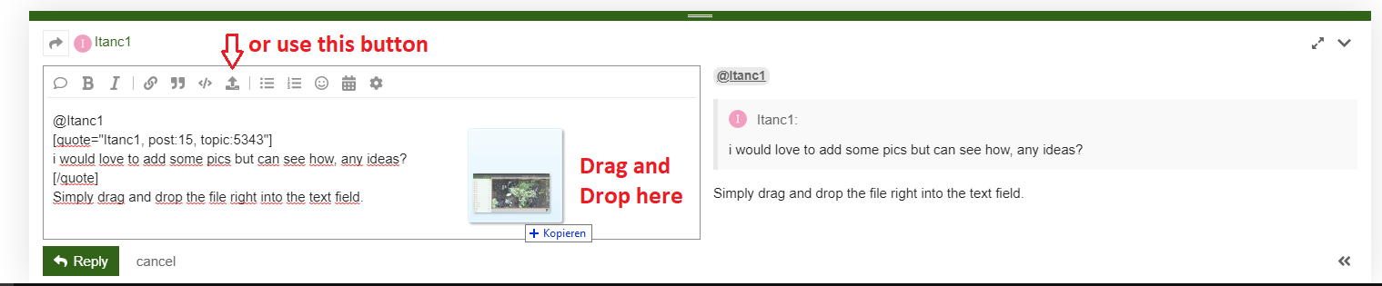
FYI rory has added a DIY section on the forum which i am using to blog my build in some detail. i would love to add some pics but can see how, any ideas?
 .
.