First Seeding, latest issues

Hi all,
I was successfull yesterday and seeded the first 8 plants! However a bit disappointed regarding the overall “performance”.
I´d like to share some insights:

  • no reliable positioning without endstops:
    without the endstops, it is not possible to reliably get a position. This is however necessary to pick up the tools. Due to elongation or compression on the tension belt regarding temperatures and overall unaccuracy of the belts, the bot is moving not precisely (within 5 mm tolerance); I even did not test longer runs on the x-axis; Endstops are mandatory to work flawlessly; the homing option needs to be build in the sequencer in order to automatically program it; one could think of an optical verification (target) before moving into the toolbay as additional security in future, but that´s very far off for now.

  • after unlocking (previously issued an e-stop) the bot does not connect automatically to the WIFI; that is the same for
    not connecting to a WIFI after power down; “I could not find the WIF access point. Check that it was inputted (?!) correctly.”

  • planting needs to be reworked; the suction is not that strong, that a seed wouldn´t fall off during inserting into the soil; moreover the vacuum still exists if the seed fully covers the needles diameter, as already pointed out by someone else;
    in addition, sometimes it “attracts” more than one seed, which then randomly fall off; one way could be to create a hole
    and then let the seed fall in from above; even more, distance detection needs to be implemented in order to measure distance to the soil; the soil is in no way even!!!

  • toolsxchange:
    is a pain right now because of the positioning errors, see above; moreover the end of each toolbay is not extending far enough into the x-axis. Farmbot cannot reach it, therefore tools fall off because they are placed too far away from the end of the “stop”; This thing is meant to be installed on the outer side of the bed, clear design error, please move the bays ends 25mm further into x-axis direction.

  • pin setting not reliable:
    during the first seeding sequences the pump did not switch off, this happened three times; could you please check if the command is sent long enough or if it needs to be resend or something like that?

  • surviving “normal” european standard weather:
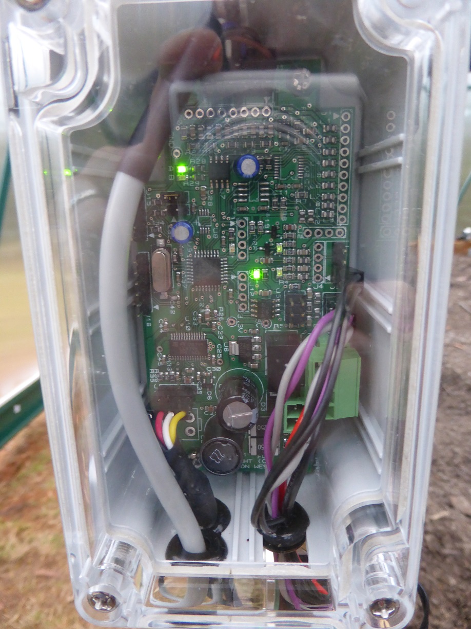
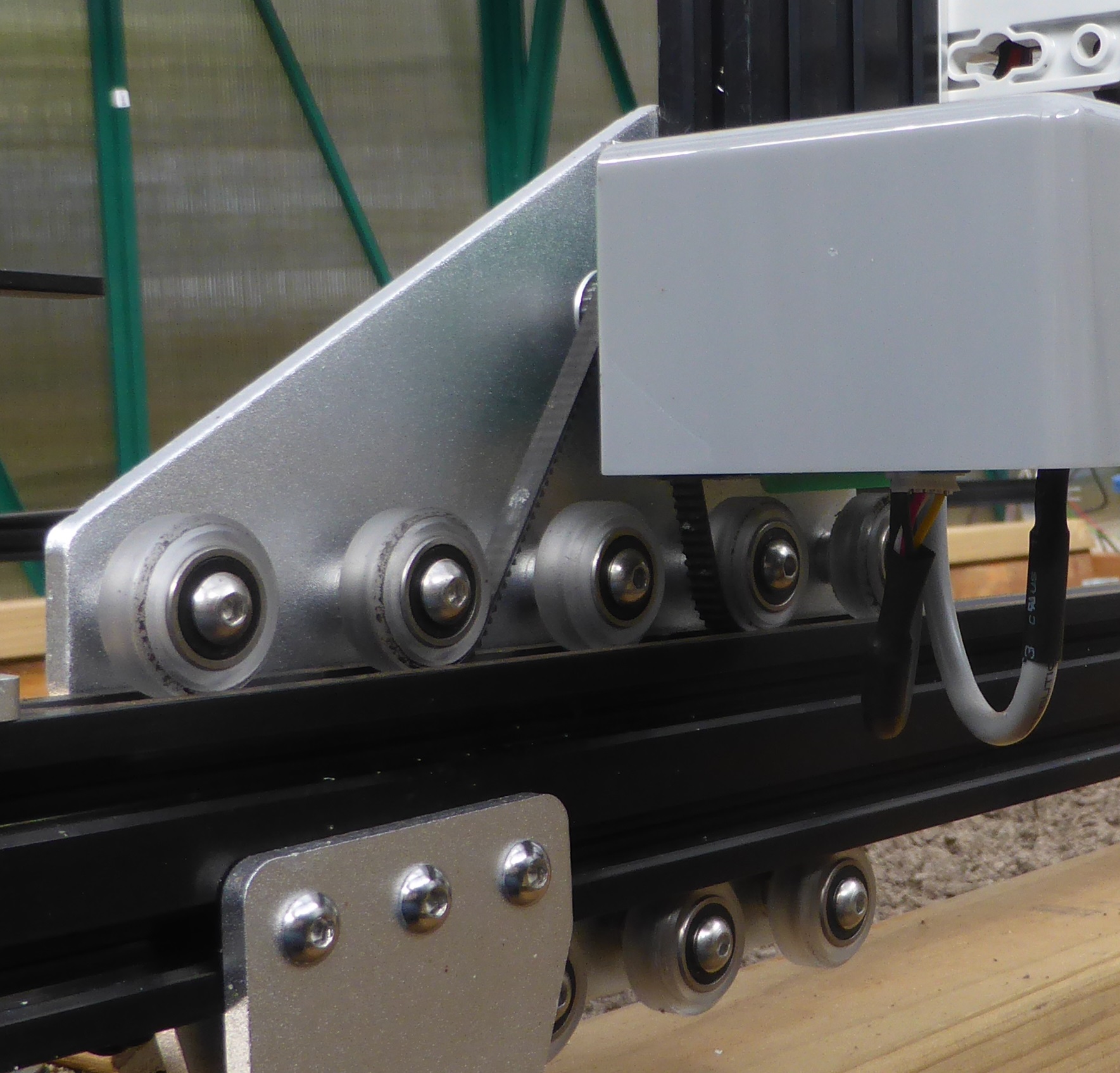
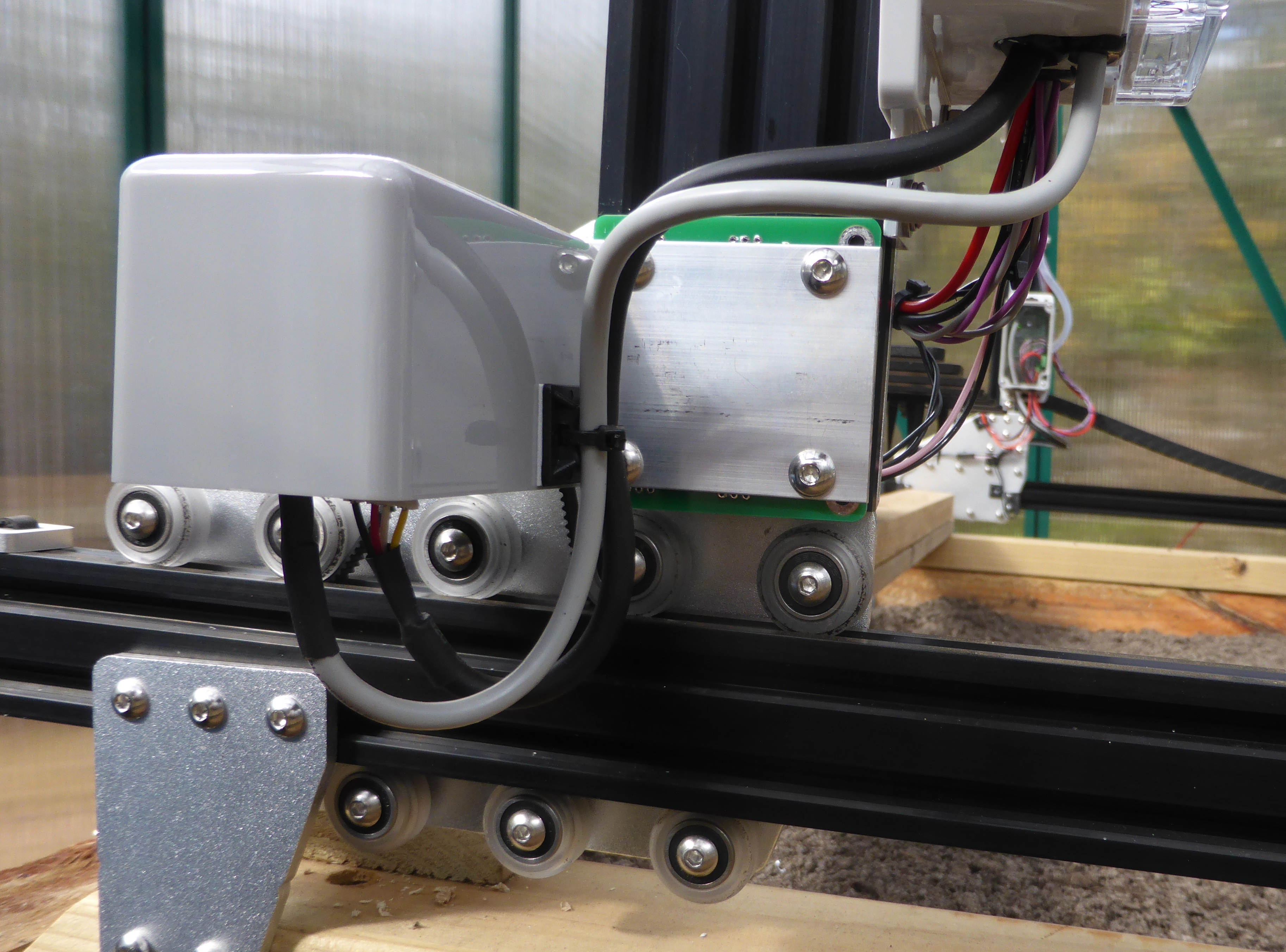
    Farmbot is sold as living outside since “2 years” and it still working; I can assure you that if I leave the motor housings open as they are, it´s just a matter of time until the “right” rain will make a short circuit and even destroy the board (?); I do not get why the housings are (at least) not a little bit extended and that “short”; I will need to rework x and y axis motor housings as well as putting some silica packs into the electronics box; during cold nights, there will be moist in there, just a matter of time… I don´t want to talk about screws and mechanical items, as this was discussed in length in another thread

  • software:
    The biggest construction site to me at the moment; several times “Farmbot did not get that”, several reloads necessary during the work with farmbot; difficulties during sequence building, trying and syncing; please always remember to code in such a way, that the user should not be able to do bad things; of course in the device settings menu this is not possible, but the syncing and saving philosophy is a good example for this;
    Please allocate all the ressources you have in the software team and get these things fixed and even “new” features - which were presented as kind of already working - implemented; I guess you might consider extending the software team to get all that work done in a sensible matter of time (until this years end)? I would love to help but that is too deep coding for me at the moment. At least I try to report each bug that flies along.

All in all, great feeling to see the bot moving, but a very long way ahead to use it for more than for watering plants…
Maybe I can upload some videos today evening…

Cheeeers
Klim

4 Likes

I agree about the endstops, that was one of the first things I added to my unit. I now use the home endstop to set a very accurate reference position, and then move away slightly so that I don’t ever hit the endstop in normal running. See this link https://youtu.be/PqFkj8dMCJU
The home command moves towards the home sensor until it is activated, then it moves away at a slow speed until the sensor becomes inactive, and finally sets the zero point 50 steps away from the sensor.

As has been mentioned before, the vacuum pump needs to be mounted on the Z axis so that the tube is as short as possible. I’ve not tried planting yet so I can’t comment further on that aspect.

The basic movement accuracy is disappointing; due no doubt to many aspects not all of which are under Farmbot’s control. I noticed that having the X motor at the top of the gantry isn’t ideal (but is there for historical reasons), so I’ve moved mine to the bottom where the mechanical forces act on the bottom of the gantry rather than the top, this improved things quite a bit. Also, the amount of cabling causes quite a load for the motors, and the load is maybe uneven when moving due to the cable duct bending etc. You can improve things by increasing the current to the stepper motors; but it’s very difficult to get right and you risk overheating/damaging the driver (which isn’t capable of driving the full capacity of the actual motor anyway).

I noticed on my unit that when the X axis stopped, the gantry (on the side with all the cables) moved a few millimetres when the motors are de-energised. Without a holding current that will always be a problem and lead to cumulative errors. You can opt to have the motors energised all of the time, but a holding current is the ‘normal’ way of solving that problem. Unfortunately the current hardware doesn’t provide that level of control, and the accuracy problems aren’t likely to be solved until the stepper driver is fixed along with reading the encoders (which again is unlikely to be fixed without moving away from the Arduino/AVR).

I doubt whether the unit will survive European weather for more than a couple of years, there’s nothing to stop water and dust ingress into the motors (via the shaft), and corrosion of the contacts (and magnets!). I’ve moved mine into a greenhouse, which stops the rainfall, but it’s probably increased the humidity so I’m not expecting much. I’ll investigate swapping over to IP68 rated stepper motors in due course.

IMO the team are doing all they can and demanding they fix this or that problem I don’t think is very helpful. By all means feed back the problems.

I decided pretty quickly to move on from the Arduino/RAMPs. I work in this field and used (and quickly ditched) Arduino many years ago. The AVR micro was fine in its day, but well past its use by date now. I’ve designed a stepper driver board which attaches to each motor, so that I can remove the motor cabling and endstops from the cable ducts. This allows me to use a stepper driver more suitable for the motor (so I can microstep and set running/holding currents etc.). The micro also supports reading encoders directly, and I get a good match between the step and encoder positioning. Here’s a video of the X/Y movement: https://youtu.be/I_Hr1SED740.

I’m now ready to start planting and watering, but not sure how much confidence I have in the rest of the software stack and/or which features are working or still in the ‘planning’ phase. So I may end up just doing my own thing. Creating and running G code files would be pretty straightforward now that the machine moves reliably. The sequencing/regimens part sounds good but seems like it might be overly complicated, especially if there continue to be unreliable/intermittent connection problems. Seems to me that the Rpi could run a node.js server and do everything locally, just accessed from any browser, no need to involve the ‘cloud’.

YMMV,
Jon

3 Likes

Hi Jon,
thanks for your detailed feedback. Would you be able to share which kind of boards you exactly designed or would
you need to transform that into a human readable format (aka wiki)? Did you tweak the software to get the endstops running as you described? Could you share a BOM? Are you generally interested to collaborate or more a sole viking? :slight_smile:

I think too that the team is working as hard as they can, but I can demand things as the whole system was sold as “working” and not “in beta phase”. If you present this picture to the public you create a certain impression of the development status. The picture presented was rather end of beta phase than alpha phase were we are currently. Therefore I do can demand, if that helps we´ll see.

Cheerio!

@Loveny, please tell us when you’ve managed to do this! I’m very interested in this idea too!

Hi Klim,

I designed a PCB to fit into a small ‘standard’ box which I could mount pretty close to each motor, so that the motor and encoder cables only had to route into the box. The PCB then just needs power (12V) and serial communications (RS485), which can be multi-dropped to all four motors.

The PCB is approximately 100mm by 50mm, and includes:

  • 12V to 5V/3.3V supply
  • micro (STM32F334)
  • RS485
  • encoder interface
  • two endstop sensor interfaces with wetting current
  • stepper motor driver (L6474)
  • one high current 12V driver (open drain)
  • one 12 bit buffered analog input
  • 8 bit buffered digital I/O
  • buffered I2C interface (5V)
  • emc/emi protection on all interface lines.

Not all components need to be fitted for all motors; only the Z axis motor needs the I2C, analog and 8 bit digital I/O for the tool head. But they can be fitted and used elsewhere too if desired. I use the high current output on the Z axis for the vacuum pump, and the X1 axis to driver the water solenoid valve.

The stepper driver is a modern type with software settable current limiting, so I can set the running current and then drop it down to a holding current when stationary. I also find that the stepper motor works better with microstepping, but you need to generate commensurately faster frequencies, which isn’t a problem if you use a software DDS technique.

I’ve connected the boards together using Modbus, only because I already use that protocol and have plenty of software that I can re-purpose. To control it I’ve simply used an existing board from another project; because it has a micro, RS485 interface and a USB interface on it. The software on this board implements the main G and F codes as detailed on the Arduino software GitHub page. But I’ve not used it much with the Rpi, so far only tested using a terminal sending the G codes. That’s why I’ve reached the point where I’m not sure whether to continue interfacing it into the Rpi, or whether to replace the Rpi software with something simpler targeted just at doing what I need.

The only real pain was making up the motor cables, in particular the motor encoder connector crimps are tiny (1.2mm) and awkward without the (very expensive) proper crimp tool.

If there was enough interest then I might be willing to explore manufacturing a few, but Farmbot themselves seem to be keen to keep using the Arduino platform.

Here are a couple of pictures of the PCB:


8 Likes

Hi @Loveny,

could you quickly summarize what would need to be done if one would want to jump from the kit system to yours?
Do you still use everything from the webinterface of farmbot.io?

Cheerio!

Btw: Would be nice if anyone from the the Farmbot Team could comment… :confused: @roryaronson, @connor, @Tim, @Gabriel, @RickCarlino

My boards basically replace the Arduino/RAMPS/stepper drivers, and the associated cabling. It also terminates the 12 way head cable on the Z axis too so that that is removed from the cable ducting. In its place you need to run 12V and a twisted pair for the RS485 comms. You can multidrop the comms and power, just make sure there’s enough current for whatever you need. The stepper motors and vacuum pump together need about 3A, so 0.5mmsq cable is adequate.

So there are 4 of the new PCBs; one for each motor mounted in a case next to each motor. The motor drive and encoder cables would need to be shortened (or coiled up) because they no longer go in the cable ducts.

There is an additional PCB which basically interfaces the USB comms (which is really RS232) to the RS485 comms for the motors. This board talks the same protocol as the Arduino, so G codes and F codes, and would interface into the Rpi in the same way the existing Arduino does. I’ve also taken the Rpi box off the gantry (the only problem with doing that is the camera, which needs an active USB extension lead and some way to ‘waterproof’ it).

Alternatively, you could easily re-purpose the Arduino to drive the RS485 comms, and leave the main box where it is (and add one of the new PCBs to drive the X1 axis, or 2 to drive both X axes).

If I was doing it again I’d probably have a slightly larger board with two motor interfaces, use one for the two X axes, and another mounted on the Z axis to drive the Y/Z/vacuum and interface to the head. There are too many options really, all with different strengths and weaknesses; the main reason for doing what I did was to fix the stepper motor driver (the Arduino/RAMPS and A4988 are IMO simply not up to the job, especially when there are better alternatives).

As for the web interface, I’m leaning towards doing something different for that too. It seems a bit overly complicated and incomplete. If I have to ‘program’ sequences right down to picking up the tools then I may as well program that into the interface board itself, the sequence is the same for all tools, just the coordinates that differ. When that’s all done, the regimens are pretty straightforward; that’s just a sequence of watering to a timescale etc. which can easily be hand-coded as a json file or something and then converted into G codes as needed by a pretty simple node.js server running on the pi, or just a simple C program doing the same thing.

So, a work in a progress, making it up as I go along!
Jon

4 Likes

@Loveny could you share a picture of the location and installation of your x motors?

Also, have you started doing your own thing? Is there a repo? I’m also very interested in a more low level way of interacting with the farmbot.

I’m also very interested in that.

Here are some closeup pictures of the X motors:-

I mounted the motors on the bottom of the vertical gantry parts, using some 3mm flat aluminium bar (which is easily obtainable here in Oz). The green PCB between the aluminium and the gantry is just a spacer to bring the overall width to about 5mm so that the existing screws are the right length.

And yes I have started to do my own thing with the software, once I discovered that a separate sequence was required for each planting (!). That takes some time though because I have a day job too. I started off keeping it compatible with the Arduino interface, but I’ve now dropped that completely and I’m controlling the motors directly from the Rpi/laptop. Because I moved to having a PCB next to each motor and controlling it all with Modbus, it’s much easier to just drive the Modbus link directly from any computer on the network (currently I’m using a USB plugin RS485, but I have some Ethernet/RS485 interfaces which will place the Modbus directly on my home network).

So unfortunately it isn’t compatible with the Farmbot kits, unless I decide to accommodate the Arduino protocol. But that’s a moving target so there doesn’t seem much point at the moment.

The Arduino interface is modified Gcodes, details on GitHub. You could pretty easily control at the low level from the Pi or a laptop, just plug the Arduino into the USB and it’ll enumerate as a serial port. Then simple scripts/visual basic/python/node.js would easily interface. The problem, as always with these things, is handling errors and unexpected events.

4 Likes

Nice mods.

@Loveny I can see the bottom of your electronics box in the last picture. Did you seal it completely? Any tips for doing that?

I cut some slots in the base, the width for 10mm grommets, then push the wires through the grommets and slide them in. The length of the slots was just right for 2 grommets pushed together. I don’t think you need to completely seal the box, the grommets are more for protecting (and supporting) the cable from the box sides. Having said that though, it certainly wouldn’t hurt to minimise the open gaps.

I’m still pondering whether to add a ‘base’ to the motor covers to try and seal the motors. Not sure that it’s worth it, unless I can seal the shaft as well. IP6x motors would have been so much more appropriate.

I did also cut 10-15mm holes and used gourmets to seal them properly, as for now and couple of have rains here in Poland it seems to be sealed enough.

Hi! I am a student from Boston doing market research on FB, and I’m looking into the Do-It-Yourself segment. I’d love to hear about your experiences with Farmbot.

What influenced you to purchase a Farmbot?

How do you feel about the current price of Farmbot?

Where did you first hear about FB?

What’s your favorite use case of the Farmbot?

Thank you so much, and happy farming!

@mulachp Please stay on topic. If you want feedback on your own question, please create a new topic. I’ve found another post of yours in another topic that asks roughly the same questions. I’ve moved those to your own topic here.