Apparently ( I’ve never done this ) you can use the Arduino IDE to “talk” to the Farmduino Express ( unplug the RPi Zero W first ) which might help isolate your issue ?
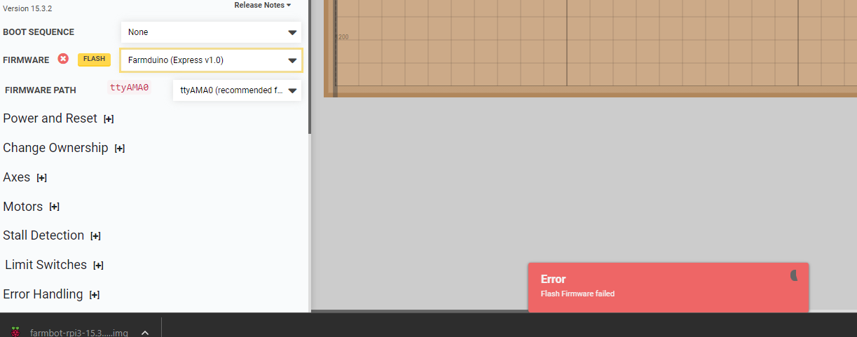
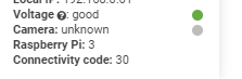
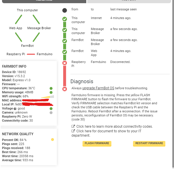
Hooked up my Zero to the app with no farmduino, just the board. The connection looks the same, so there’s no talking at all between the Pi and the Farmduino. Feeling hopeless here
Marc from Farmbot said I should just buy the whole electronics box in September, which means I wasted my funds on the Farmduino and all Pi Zeros/2ws.
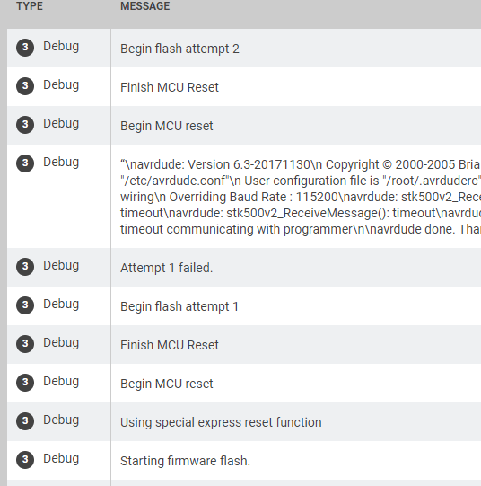
You could try to fiddle around with that reset function. This was a fix for my device a long time ago when I had similar issues and the same log output. Simply keep the reset button pressed until the flash starts. This will most likely take a few tries until you find the right timing. In my opinion its also easier if you can upload a sketch using Arduino IDE, but you would need a TTL USB converter to access the rx/tx pins on your farmduino.
Are you confident with those “press-fit” 40-pin header connectors that you’re using ?
( seems to me that they would depend alot on the integrity of the plated-through holes and the connecting traces on both the Farmduino and the RPi PCBs !)
They appear to be the major difference between your DIY and a FarmBot Inc. electronics box (?)
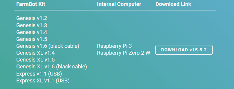
That’s what I mentioned earlier . . the correct FBOS disk image file for RPi Zero 2 W is named farmbot-rpi3-15.3.2.img ( this is because the Zero 2 W architecture closely resembles the RPi3 B Plus )
Really good point, that I didn’t even notice. This is really important and should be checked. Even though it would be really bad luck if all 3 Raspberries would not get proper contact.
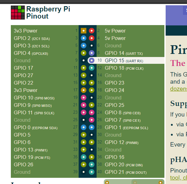
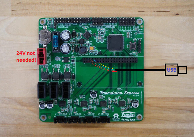
I just painted the connection layout using colors that are good to see. The colors of your cable are most likely different. You should also check if your converter does have a 5V output to supply the Rpi and the serial bus gate U6. This way you should be able to upload firmwares to your arduino using a generic Mega 2560 in Arduino IDE.
In the following picture, its wired like this:
Red : +5V on pin 4 (2 works aswell)
Brown : GND on pin 6
Blue : TX on pin 8
Yellow : RX on pin 10
‘Are you confident with those “press-fit” 40-pin header connectors that you’re using ?’
I was not confident that the ‘press-fit’ were working and have been soldered (the newest 2w didnt use a ‘press-fit’ at all to rule this out, so I used a traditional soldered one) None of them are seen by the Farmduino.
At Marc’s request, I checked if the 5v and 3v pins were getting power (with a multimeter) and they were. A bit after that, he said I should buy the electronics box assembled when available.
" Even though it would be really bad luck if all 3 Raspberries would not get proper contact."
If Im being honest, being told to buy more after having some evidence the Farmduino I just bought doesnt work, doesnt feel very good.