Camera Calibration Tips and a Question

Executive Summary of my Question
Updating my question. After further experimentation, if I use a default FarmBot camera calibration (i.e. using the calibration card and specifying an object distance of 100 mm), I get a pixel coordinate scale of .6154 and the pictures alone the X axis align well – but not the Y axis. If I fake out the calibration and tell the calibration routine the red dots are only 66.25 mm apart, I get a pixel coordinate scale of .4062. In that case, the alignment along the Y axis is good but not along the X axis.

What strikes me is that the camera resolution is 0.3 MP which is 640 x 480. The calibration routine doesn’t try to figure out the camera orientation with respect to which is 640 and which is 480. Is that the root issue here?

I’m somewhat stumped. I feel like I have a good process in terms of a golden image with tight detection. But I don’t see how to get my pictures overlapped correctly in both dimensions.

Details for the Curious Including Some Tips (ignore this if you are not curious)

I have a Genesis 1.5. If you are just getting started with camera calibration, it has two goals

  1. Determine the orientation the camera is hanging. Think of this as 0 degrees to 360 degrees in relationship to the origin of your FarmBot.
  2. Determine how the camera image size relates to the physical world – how many pixels do you have per mm of physical space at a given height.
    In order to do this, they give you a nifty card with two red circles that are exactly 100 mm apart. The card has 4 quadrants and one of them has a home icon. If you situate the card such that the home icon is toward your origin and you take a picture, then you can a) tell the orientation and b) knowing that the dots are 100 mm apart, you can tell how many pixels gives you a mm.

I have some tips I’d like to share that I used.

  1. Before doing anything with the calibration settings (i.e. with all calibration data cleared), go out and put your Farmbot near a corner edge of your bed.
  2. Take a picture and examine the orientation of the camera to try to get the camera aligned with your bed – in other words, with no calibration settings applied, you want the camera to look down squarely on the bed. Doing this will help eliminate problems with images that need to be heavily cropped after rotation.
  3. Adjust the camera and then take another picture. Repeat until you have good alignment.

Now we are ready to start with the software side. For me, during the day my calibration card (as well as 3d printed red golf tees) were washed out by the sun. I got my best results closer to dusk.

Get a Golden Image
This part is critical. You don’t want to use the calibration function over and over because it takes a new picture each time. With each new picture, you get new variations (especially of light). What you want to do is to end up with a picture that you can scan multiple times and get the same calibration result each time. The importance of this will become clear.
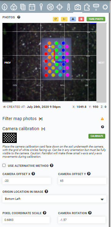
Take a picture and then select “Scan Current Image”. You’ll have to adjust hue, saturation, etc. until you get a good calibration image. You want something like this:
image

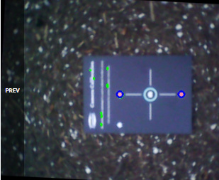
In this image, you can see that the calibration dots were cleanly selected and hence I have high confidence in the final result. If you didn’t get this, then you should adjust your settings (Hue, Value, Saturation) until you can get something like this. It won’t do you any good to go forward until you have a golden image. In my case, the golden image is this:
image

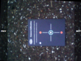
In other words, it is the raw image without calibration marks.

Fine Tune Your Calibration
I got a great golden image and a clean calibration. But, when I took photos of my entire bed, it was a mess. Images were much larger than they should have been and the FarmBot overlay of tools and seed trays didn’t match the image.
Remember, the calibration is only figuring out 2 things – the rotation and the pixel to real world ratio for a given Z height. Since my images were too big, I determined that I needed to reduce “Pixel Coordinate Scale”. You could adjust the pixel coordinate scale value directly as it is an input box but don’t because you can’t later do Weed calibration – the scale has to be close to what was determined by the calibration routine.
Instead, lie to the calibration routine about the distance between the calibration object points. In my case, if I tell it the objects (the two red dots on the calibration card) are 66.25 mm apart then I scan my golden image, I get a lower pixel coordinate scale.
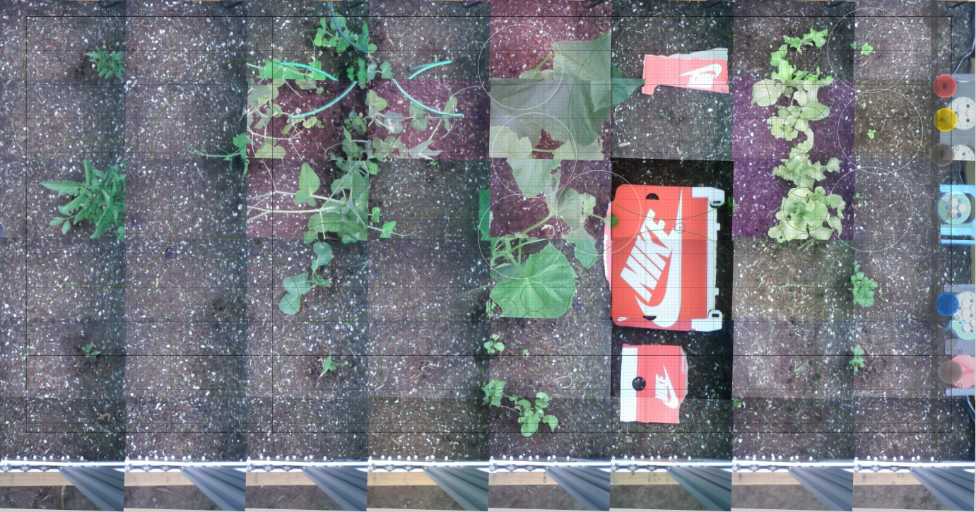
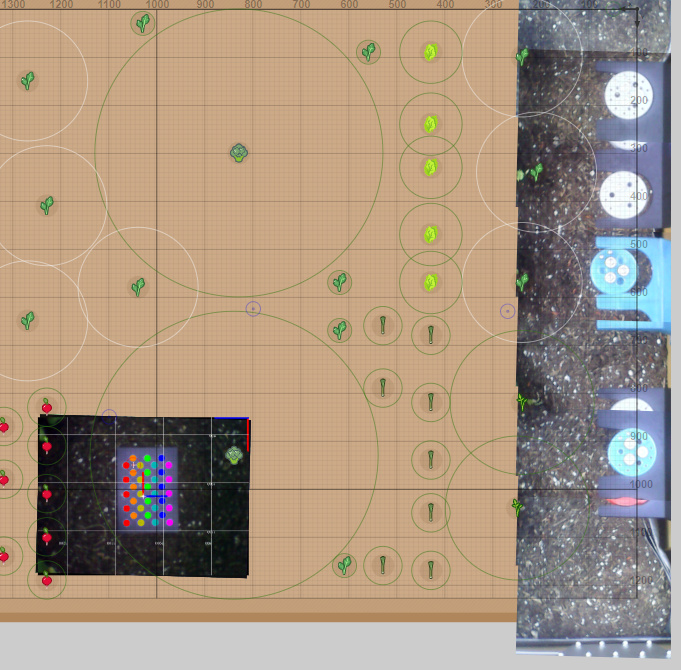
When I take a photo of a row on my FarmBot, it looks like this:

You can see there is still some room to tweak the angle but things line up pretty well. The question I have is why, when I specified a 100 mm object separation distance, did I get such a bad result.

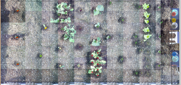
After further experimentation, when I take this approach, the single row as shown above looks good. However, for an entire bed, things are not aligned. One plant will show up as two plants because the pixel scale is off. I re-ran calibration using the accurate object distance of 100 mm.

Using the truthful object distance and calibrating, the rows above are not aligned but the columns are as you can see below.

image

5 Likes

I’ve updated the scenario above. Net is that I can’t see how to get both dimensions aligned despite having a pretty good process (I think).

1 Like

Thanks for the detailed report of what you’ve tried. Can you confirm with a measuring tape or ruler that when you tell your FarmBot to move 100mm along X and Y, that it actually moves 100mm? It is possible that if it is moving a scaled amount, that would mess up the spacing of images.

1 Like

When I saw your suggestion I immediately thought “that’s got to be it”. I took a few measurements

  1. I mounted my DIGR tool which is a simple spike. I moved to a position and lowered the FarmBot to mark the spot.
  2. I moved in Y dimension 100 mm and measured with my calipers. It looks like 99 mm.
  3. I moved in the X dimension by 100 mm and measured and got 100 mm
  4. I took another reading in the Y dimension. I set my calipers to their maximum distance (157 mm) and made two holes 157 mm apart. My calipers were a little long - about 1 mm or perhaps 2 mm.

I did one final measurement on the Y axis because, if you look above, I had to lie about my distance significantly just to get the first row images to align and the movement was only along my Y axis. So, I focused on the Y. I took readings at the maximum distance of my bed which is 1228 mm. I measured the distance between the holes. It was more than 48.25 inches and less than 48.5. I estimated 48 3/8 which is 1228.72 mm.

Open to any other ideas.

1 Like

@jrwaters I’ve been thinking about this in the back of my mind the last few days wondering what is going on with your setup. Nothing comes to mind and I’ve never seen this problem before, so I’m pretty stumped.

Can you try the new camera calibration method via dot grid as described here? Let me know if this helps!

Hi @roryaronson,

I’d be happy to. I should be able to get to it Wednesday night. Thank you for the suggestion.

Jack

Hi @roryaronson

I love the new calibration approach. During the day, I couldn’t get it to work and couldn’t see why but I knew from experience (and your docs) that I should wait until the evening. I was able to do it at night using the FarmBot lights.

You can see the results below which are similar to the original calibration where I didn’t lie.

This time I around I also use Z=0 instead of Z=-50. Obviously I use the same Z value for calibration as taking pictures.

The end result though is the same, I’m afraid.

In the image to the right, you can see that my standard Tool bays are compressed. I have an extra tool bay which is the blue one in the middle and it holds 2 tools and is also compressed (or overlapped or whatever).

The only other thing I’ll mention is that I’m using the camera that came with my Genesis 1.5. Even though I had the “black picture” problem, I replaced my USB cable and it has mostly been fine since then. I didn’t want to get a replacement camera if it wasn’t needed. Is there some other characteristic or difference with this camera???

Thanks
Jack

Thanks for trying out the new calibration technique - glad you got it working in the evening :slight_smile:

I’m still scratching my head though as to why you can’t get images aligned well along both axes :thinking: I’m not sure this info is going to help at all but I’m getting a bit desperate in trying to troubleshoot this haha. Can you provide:

  • Microstepping, steps/mm, and encoder scaling values for X and Y axes
  • Web browser and version you are using

An experiment you could try: lay down a ruler or measuring tape in the garden (preferably with metric ticks) and take photos of it and see if the ticks match up with the grid along each axis. I’m not sure what that will tell us if anything.

Oh! Are your toolbays located near the soil surface or significantly elevated? Calibration allows the bot to find objects in a Z-plane at the calibrated distance from the camera. If your toolbays are significantly closer to the camera, then they would appear much larger in the map when things at the soil level are accurate, which seems to be the case for you.

1 Like

Hi @roryaronson,

Yes, its strange! I don’t mind providing info (and I see your other post too). For this one:

Microstepping is 1 step per unit (default)
Steps per mm is 5 for both x and y axis (default)
Encoder scaling is 5556 (default)
Web browser is Google Chrome Version 84.0.4147.105 (Official Build) (64-bit) (this is latest version)

I’ll see if I have a metric ruler though looks like your next post might reflect the immediate priority on this.

Thank you!

That is a wonderful point that I should have thought of! In hindsight, it doesn’t seem prudent for me to have used something not at soil level to sanity check the calibration. I think you are onto something here.

What i will do, is set up something at soil level that allows me to assess. Perhaps a continuous image where I can see if it is aligned. All I really care about is the soil level!!! So, if this looks good, we will put the issue to rest.

FWIW, my tool bays are between 140 mm and 190 mm above the ground. More when I run other test.

Great catch!
Jack

1 Like

I’ve documented similar image positioning issues where I also came to the conclusion that is caused by a lifted toolbay. I wasn’t able to get the coordinates to fit the pictures while the tools are properly located in the pictures. Issues and experiences with (USB) camera calibration.

2 Likes

Ok - I didn’t have a metric ruler but I had something similar - a Nike shoe box. I put pieces of it on the ground and . . . it looks like things line up!

The leaves of some of my taller plants don’t look quite right (cucumbers to the left of the box) but I suppose that is the nature of the beast. For weed detection, it matters what is on/near the ground.

I really appreciate all the help and comments here!

Thanks
Jack

5 Likes