Hi Guys.
I’ll be using this forum to document a journey I attempting to navigate.
Essentially I am attempting to build a platform on which one FarmBot MAX will service multiple beds.
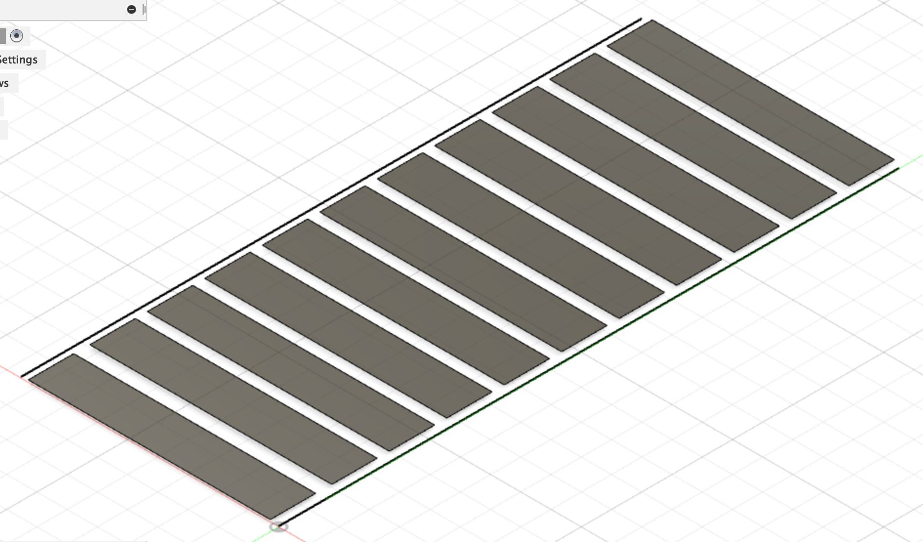
To start with, we are working towards one FBMAX servicing 12 parallel beds. In order to accomplish this I have to develop a rail system turning THE WHOLE x-axis into a gantry on 41m rails.
CONCEPT:
FBMAX will complete a programmed series of scripts on one bed over a timed period for ‘X’ number of units.
After a delay, (say) 5 minutes, FBMAX will move along the 41m rails to the adjacent bed.
FBMAX will then duplicate the original “complete a programmed series of scripts on one bed over a timed period for ‘X’ number of units”
Then the delay will reoccur.
This will occur for each bed.
I have identified a few issues, and I look forward to all of your nit-picking and concept-questioning as we move forward.
Excited about your constructive input
Adam
One obstacle I have identified is the inconsistencies I will experience in the terrain when setting up 41m rails. As such I want adjustable mounts. And I want to PRINT EVERYTHING!!!
The adjustable mounts will also assist in reducing the time taken to setup a FBINF on uneven ground , and on poor, or different soil types.
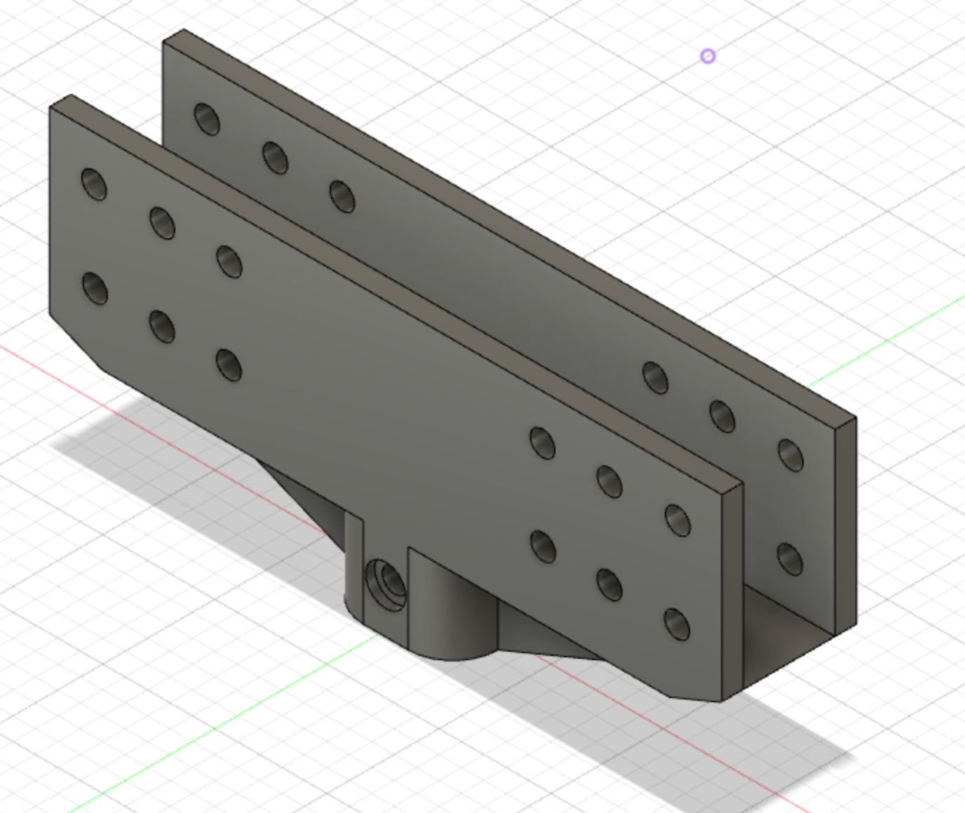
This threaded portion is designed with an M20 thread, and large lateral support with M5 bolt locations to join 2060 v-slot rails.
After loading this into a slicer, I have changes to make already as it’s not a pleasant design to print.
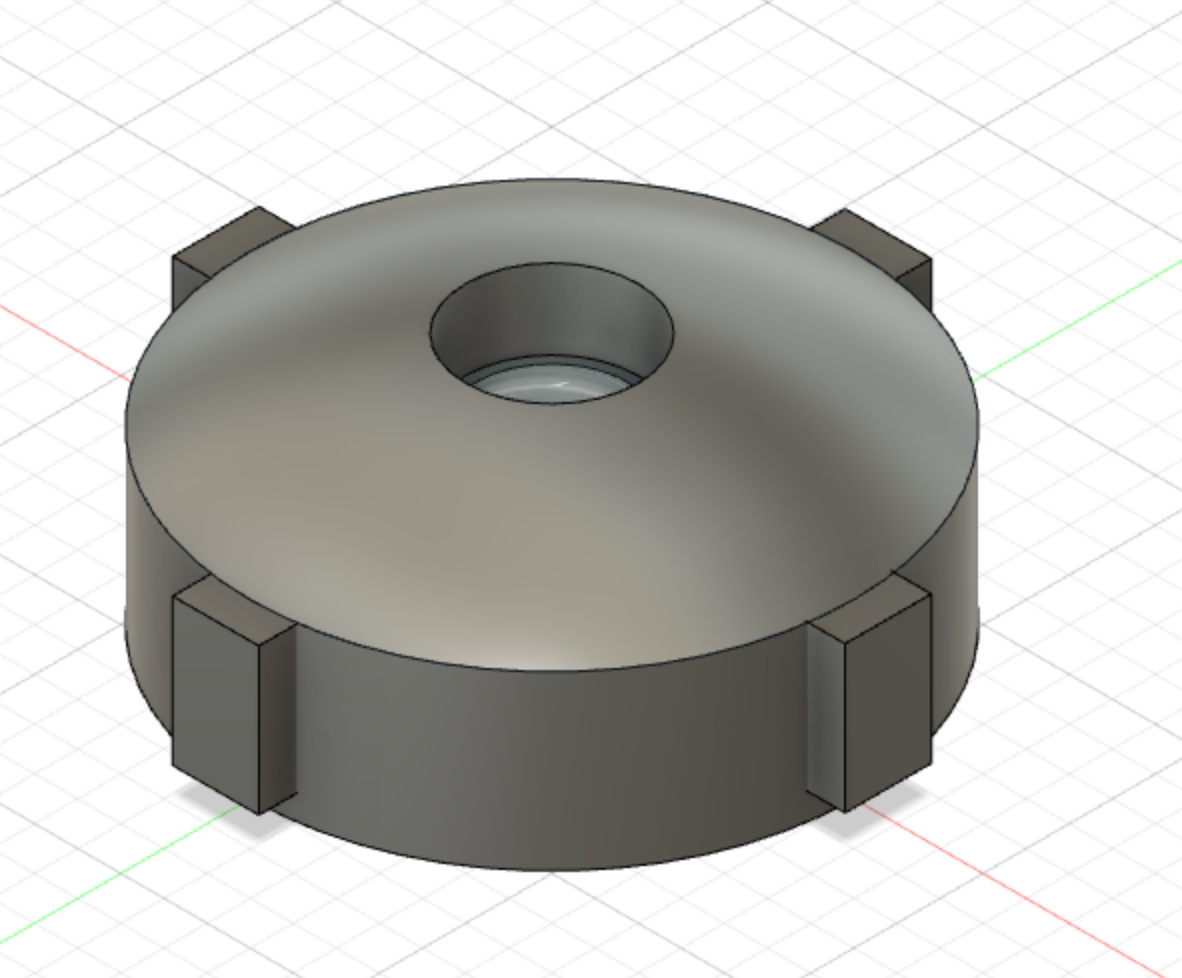
This nut portion has a dome like your shoulder and hip rotator cup. It also has an M20 thread and is 70mm in dis. It’s larger design with a large surface area should make adjustment without tools (by hand) easy.
I have concerns about the rails being unable to remain vertical, and expect that I will require internal and external, light, triangulated bracing supporting the 41m rails.
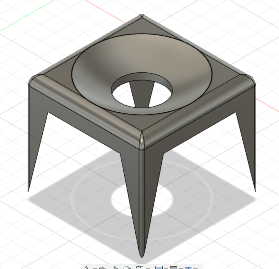
This is the mount. The dome is to accomodate the dome on the adjuster nut. It has 60mm clearance allowing a wide range of adjustment.The four legs are pointed thus guaranteeing the mount has a solid footing and good penetration into the terrain substrate. This mount is designed to work on rock, sand, soil, grass etc.
I’ll get working on an easier to print version of the threaded portion…
removable threaded bar from mount to make printing easier. (Thinking of making female thread in mount, and then printing the mount and the thread separately).
going to go with ACME thread for greater thread surface area.
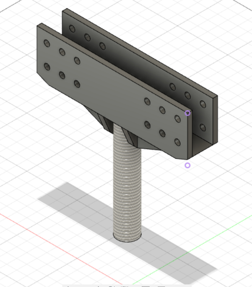
I have removed the external thread and this will be printed separately as a threaded rod.
The small recess on the left face is to use enable the use of a screw to mechanically fix the threaded rod into the platform.
Thread changed to 3/4 ACME thread.
It would be helpful to see a diagram of the whole system. I may have attempted to do some of this already just need to understand exactly what you are trying to achieve.
Am I right in thinking you are using the threaded mount to raise and lower the 41m rail so it is level?
You are right thinking that the threaded mounts are to raise and lower the 41m rail so it is level.
I’m aiming for about 150mm of adjustment per mount.
How do I plan to move the FBMAX along the rails?
(PLAN!!)
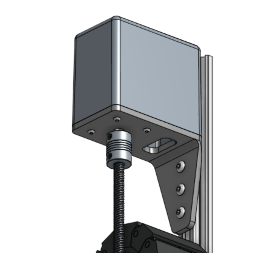
An Arduino with H-bridges paralleled to twin NEMA 17’s on each rail. Probably just use something like the z-axis motor mount FBot already use.
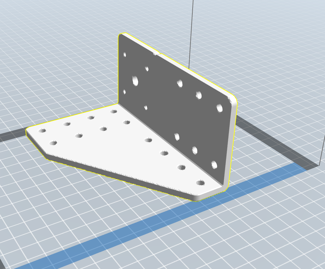
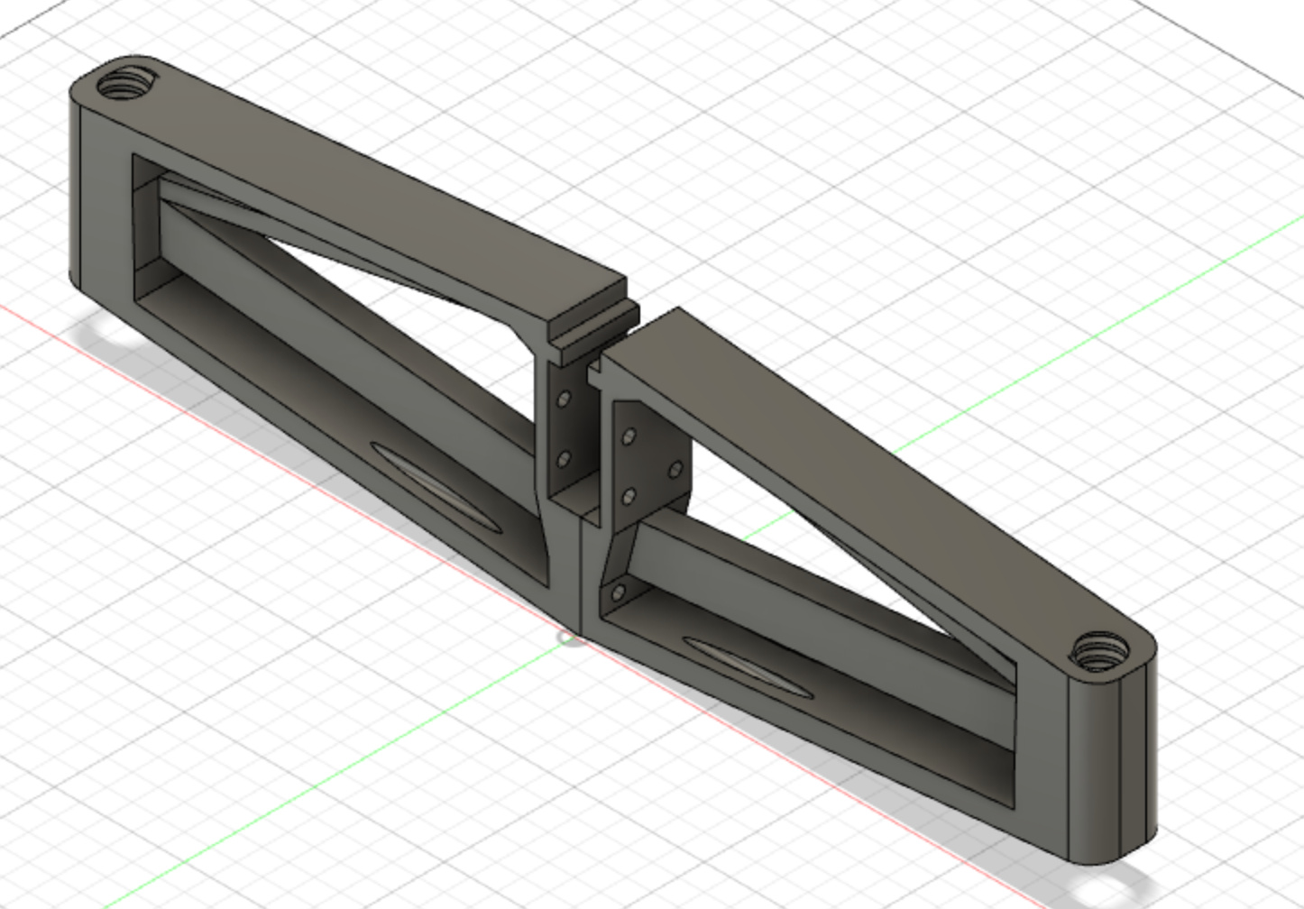
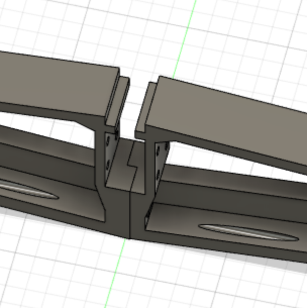
I’ve created an stl file for printing which uses abit of bracing.
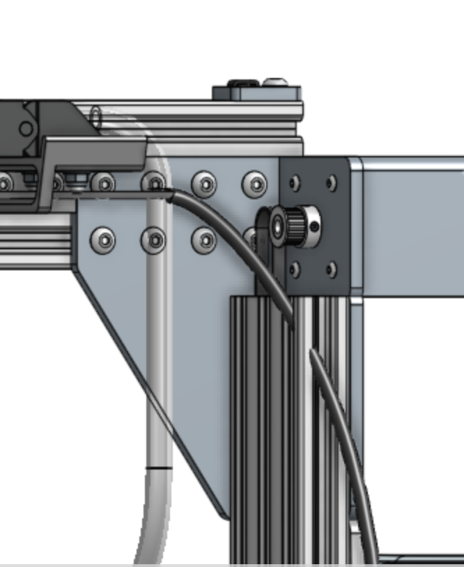
FBot (aluminium) z-axis motor mount:
Why 41m?
I had a goal of using 8 FBot’s to service an acre (running before walking…) because I listen to a lot of podcasts by Diego Footer, Curtis Stone, and JM. They talk alot about micro-farming 1/8th of an acre, and they talk about “buying” unto 40hrs of labour to achieve this.
Noting I am in Australia and we have ridiculous labour costs, I want to reduce labour costs (a whole other conversation I am happy to have ) to reduce the costs of healthy food. Good food should be available to everyone!
Therefore, if I use 41m rails for one FBMAX, I will require only 7 FBot’s to the acre, BUT if I have to reduce the rail length, and employ another FBot (for one of many various reasons I am not even aware of yet), I can still achieve my goal of 8 FBot’s to the acre.
In a nutshell - 41m rails builds in a safety margin to achieve my goal
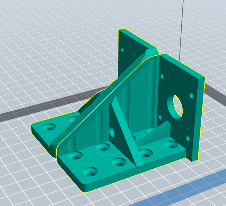
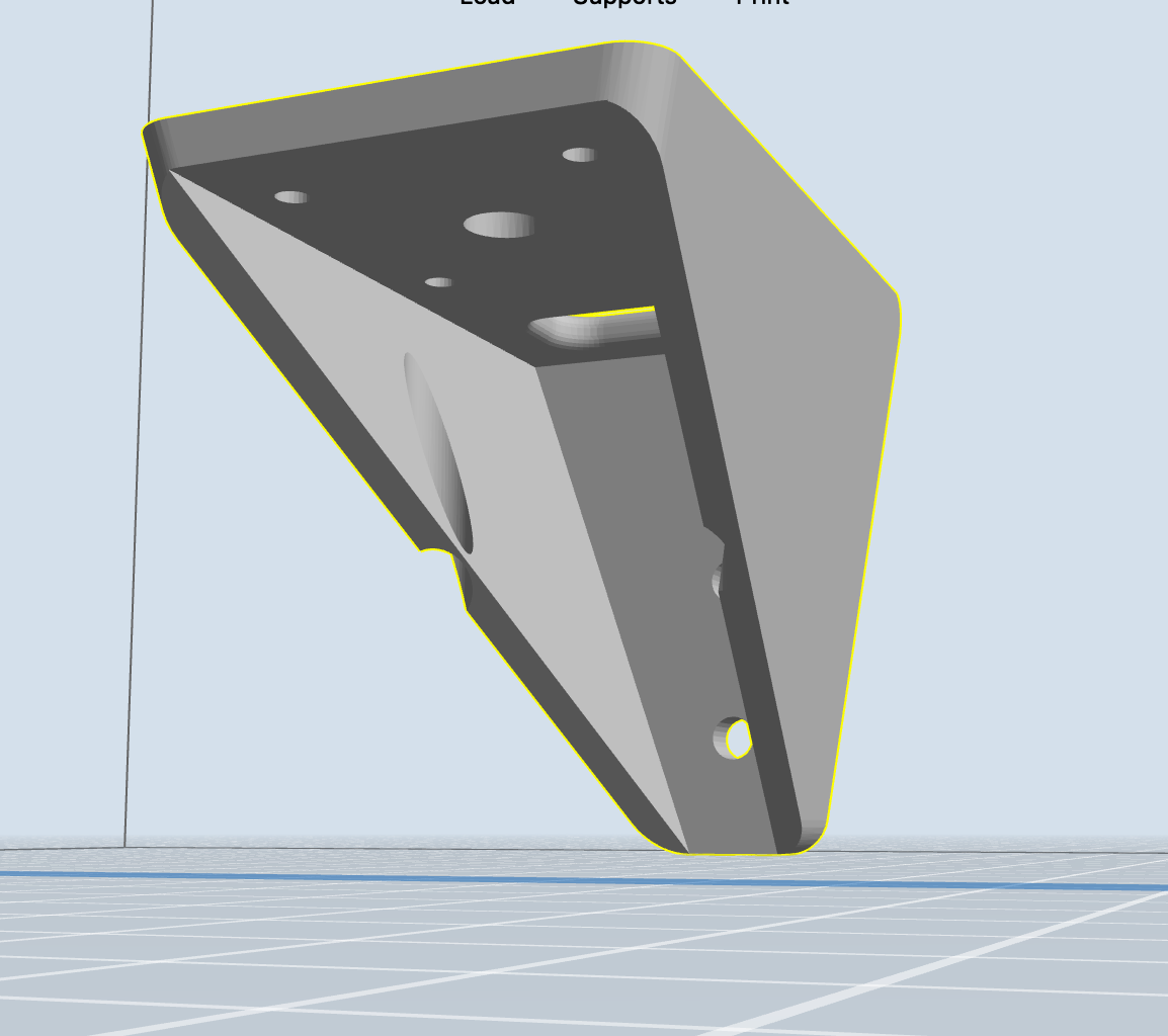
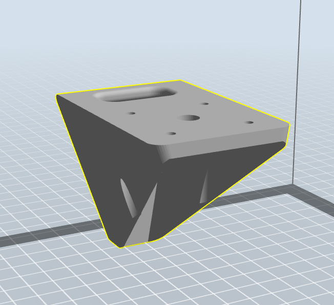
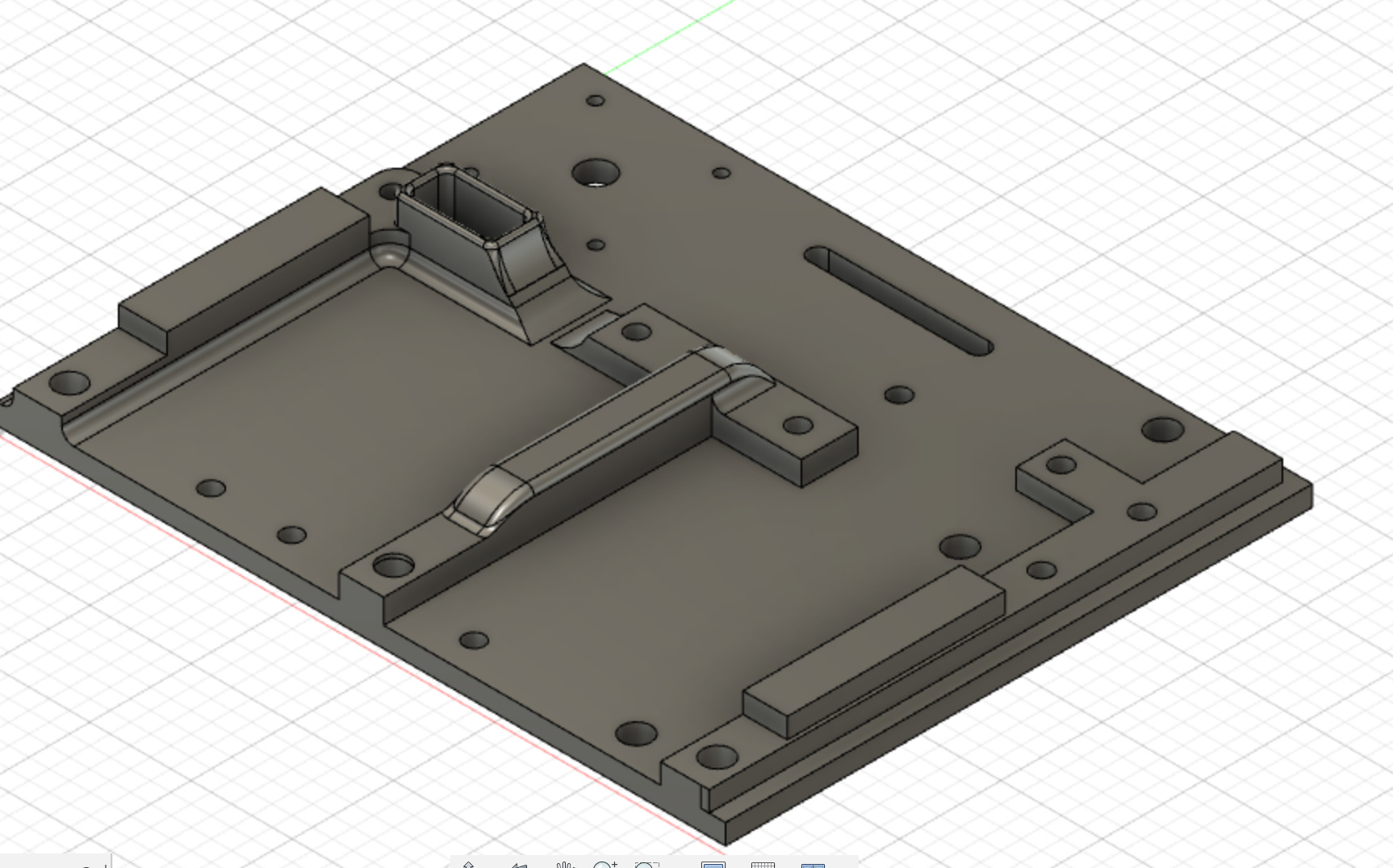
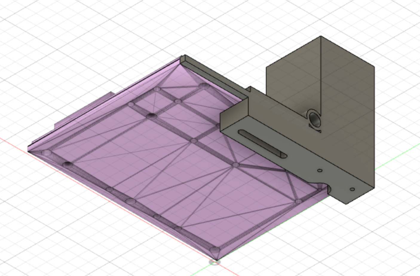
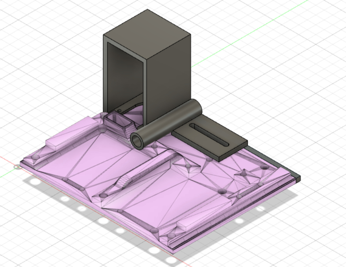
I have created print files for the cross slide and also combine Horizontal Motor Housing/Z-Axis Cable Carrier Spacer Block into a brace.
This is the proof-of-concept version and I still have the following to do:
Reduce bracing on cross slide and add it to the brace,
Chamfer of edges,
Radius of edges,
Refines tolerances,
Locating cut-outs.
I tried using threaded rod to level a Farmbot but it proved to be extremely wobbly even with bracing. I switched to linear rail which was much more stable.
I know I said use ABS to print brackets but if it’s too much of a pain PETG would probably work and be easier to print.
I suggest you build a smaller prototype first, before you spend a lot of money and find out plan A doesn’t work. I would build 2 beds and make sure you can reuse as many of the materials as possible if it works and then add on the other beds.
Whitecaps, the current concept is to use timing belts, however, I’m struggling to find any data on how much they stretch over a fixed length. I expect stretch will be an issue.
I’m open to also consider:
Bicycle chain (which could easily be adapted to NEMA 17’s however it might be expensive, but won’t stretch),
Stainless wire,
Geared linear track - however I’m sure this would get debris in it - I could overcome this. I would probably need to build a custom 3D printer though as I’d want 3m lengths to reduce joins. (This is my preferred choice, and I have the room for the printer).
I believe my 41m rails will be wobbly prior to being supported.
I am looking at bracing the rails with a triangulated, printed brace which will have securing pins into the adjacent terrain. I’ll get an image of this tomorrow.
I will only be bracing them where the FBMAX will locate after it travels. This is to say, I would only require 12 braces on each rail.
I’ve checked out PETG. I’m going to buy a few rolls to give it ago. My concern is the glassing temp. It get’s hot in Australia’s sun! But if I don’t try, I’ll never know!
Is that advice or concern regarding the prototype (Thanks either way )
The prototype will be 4 beds of 3x18m, but only 3x3m in each bed is to be serviced for the proof of concept.
Lol both. Prototyping was a big part of my last job. I always go in welcoming mistakes/ideas that don’t work as it means progress, so long as the cost is low. I tend to ask if plan A doesn’t work how much of plan A can I use for plan B, C etc.
Guide ropes and ground anchors might stabilise the 41m rail you could try thicker threaded rod too.
You may get away with belts if you have sensors at the start of each of the beds. Then stretch doesn’t matter as much, as you only need to stop in 11 places and not between those places. If that makes sence i.e. the requirements on the 41m mean you only need to be exact 11 times.
I was thinking along similar lines, but rather using a self leveling robot frame to move and position it rather than rails. The trick is the precision positioning, but for ag purposes within 1 inch or 2.5 cm should be close enough on each bed. The capacity to recognize weeds seems similar to a dynamic photo memory and positioning that could adapt as plants grow. This would make it possible for a single small unit to do one or more acres. Why not maximize efficiency and run each unit continuously?
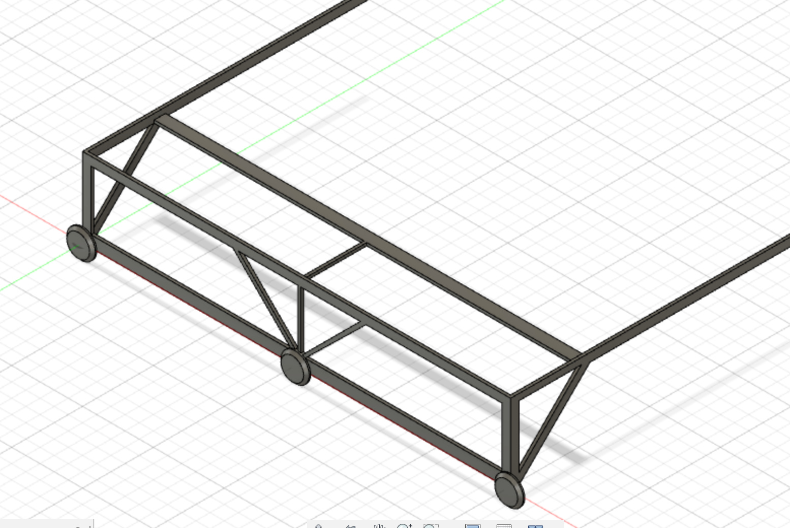
A guy at work has worked on a few autobot, and autonomous vehicles using Pixhawk as a control system (among others…).
His recommendation is a deisgn like the below image, whereby I add a subframe to the end of each FBMAX (making it about 19m overall in length). This subframe would have a minimum of three 200mm wheels and they would move the FBMAX from one bed to another. Bear in mind the image below is for delivering the idea as a picture and doesn’t include all bracing.
YES!!! (at the risk of sounding like Tyson Chicken )
My desire for maximum efficiency is because I not only care about reducing the cost of fruits and vegetables for every Australian, but I also am very aware I need to feed my soil microorganisms, mycorrizeal fungi, increase organic matter, and increase soil water infiltration. If I can reduce labour costs, I can therefore reduce the need to grow only profitable crops, and I can include beneficial flowers, cover crops and nutrient dense plants such as confrey. This is very important as I’m bit of a believer in the ‘food is medicine’ mantra
Oh and while FBMAX, or FBINF for that matter might need maintenance, it’ll work in the rain, before sun up, after sun-down, and doesn’t need sick days, christmas off, and will never be hung-over
anyone in touch with https://pixelfarming.eu/ ? It’s in Dutch, so that may be hard to digest.
Basically, it’s a research center that has the same idea: create a robot to automate organic farming. I think I once saugh a pixture of a farmbot on wheels.
They are putting a lot of effort in a portal where customers can rent farming land and the service to grow meals on that land. They’re launching a new robot soon. very exciting!
I’m also working on a robot in my spare time. Imagine a robot lawnmower had babies with a rototiller I’ve shared progress in this thread:
Oops, 't has been a year! I’ll post some pictures of the current prototype as soon as we have sunlight…
1x roll of Esun PETG on order,
All the hardware required for the cross slide is ordered (and was meant to arrive yesterday, but you know - public holidays!!)