as I am trying around with write and read pins and the status information, I am missing some information / documentation.
Which features are already implemented?
can I read the soil moisture sensor? How?
can I use the tool verification digital in? How?
what is the idea of communication about the write and read pin events, my log in the web api (my.farmbot.io) seems to be mixed up during debugging? It always says 8:31 am, I guess the time is not set properly how can I check that?
is there any documentation about the parameters which can be used in the send message line? like the coordinates?
pin numbers are the Arduino numbers, right? according to this docu https://genesis.farmbot.io/docs/plug-everything-in I could read pin 63 to know whether the tool is mounted or not, meaning if the 5V are connected to this digital input, right?
If I do this it says SET PIN: 63: 1023, even if I used the read pin sequence, great and now?
I am missing a huge information package here, maybe I did not find it, maybe it is not yet implemented. Could someone tell me please?
@roryaronson: I am more than willing to update the documentation or wiki or whatever to help other future users not spend their time on things I did, because of a lack in the documentation. What is the best way to do that?
You can read the soil moisture sensor by reading the pin you have UTM pin D (the soil moisture sensor signal) connected to on the RAMPS board. D59 (A5) is suggested in the documentation. You will want to read the pin in analog mode (PIN MODE 1 in the web app). The reading will be an integer between 0 and 1023, which corresponds to a voltage between 0 and 5V (see analog read and soil sensor hookup guide for some general info).
To read the tool verification pin, you can use the digital pin read mode (PIN MODE 0 in the web app). You will then get a reading of 0 if the tool is not connected and 1 if the tool is connected.
The ticker log times will be corrected in the next web app release.
The coordinate variables included in the default message in the Send Message step are the only special variables. When we add more, we will provide documentation for them.
We’re aware that the read pin log message text needs to change. The value in that message is the value read from the pin.
thanks for the fast answers!!!
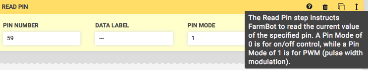
Maybe you should change the message box when moving the curser over the ? for read pin.
I did not know what 1 or 0 meant:
Regarding the logging and read outs etc. What is your philosophy behind these information?
In my opinion there should be two “modi”:
debug
normal operation
For debugging one needs to know the information of read outs comfortably. This could be done via the log messages,
but at the moment it only shows the latest information in the upper bar. If I click onto it, everything is mixed because of
the wrong time.
For normal operation it would be nice as well if I could look up in a log file or somewhere else which soil moisture it measured and which actions it took depending on if clauses etc…
Could you please elaborate on the logging philosophy?
For all sensors, will it be possible to insert calibration curves somewhere? E.g. for the soil moisture sensor…?
The level of detail of log messages is up to you. If you read a pin, there will be a message for the returned value. Beyond that, you can use If statements and Send Message sequence steps to add as many additional messages as you’d like.
For all sensors, will it be possible to insert calibration curves somewhere? E.g. for the soil moisture sensor…?
The log is completely mixed up, is that connected to the know bug with the wrong time stamp?
What is the way of reporting the wrong label above in the screenshot? Raise an issue within github?
Momentarily I only can send the positions x, y and z via the sequencer and custom text, right?
Is there any way of having data viewed from the database? E.g. which plant took how much water over the lifetime etc.
pp.? I saw that I needed to install some graphical packages, I assume to draw graphs…?
For reporting any software bugs, opening an issue on GitHub is preferred.
I believe you can send other values in the Send Message text, but I’m not positive as I can’t find the documentation for that. @RickCarlino can you chime in with the allowed syntax/variables of the Send Message text? I’ll add it to the software docs once you verify.
Right now there is no way to view the data from the database, or add calibration curves, though those are definitely on the roadmap!
Do you mean that the “if” function can not use pin 59 because in the drop bar are only pin 1 - pin 13?
In this case you need to create a sequence in which you are first reading out the sensor value with “read pin”. Make sure a valid data label is used. Then you can use the “if” function with the desired pin that you set earlier.
I recently heard that there is only a temporary fix right now. In the next patch you will be able to select the desired pin (f.e. pin 59) directly in the IF function.
I wired a distance sensor which outputs 0 to 5 V to different analog inputs and got a very interesting finding:
As soon as I connect the output of the sensor to one of the analog inputs it gets pulled up to either 3,3 V oder 5 V (power 5V and ground are connected to the ramps shield as well). I measured this inline with a multimeter…
If I disconnect the analog in from the RAMPS it works flawlessly with a multimeter between one RAMPS GND pin and the sensor output… as I tried on the Arduino side I am sure that the signal output cable does not make a short somewhere.
The pullup resistor can only be ignored for low impedance sensor outputs. If the distance sensor is a Sharp IR type then they have high impedance outputs and a pullup resistor will likely cause the output to be permanently high.
Why would you need an input configured for analogue operation to have a pullup? It makes no sense at all. But if the Arduino is supposed to be able to read analogue sensors then some input conditioning/scaling/buffering/protection circuit would be expected.
Hi @Gabriel thanks for the fast response. It does not work, as I described in my post.
Makes sense and that it was I get.
@Gabriel: Is there any way to turn off the Input_Pullup? I really do not get which sense it makes for analog inputs other than making some setups of analog measurements impossible?