This article guides you through troubleshooting movement issues. You’ll start troubleshooting with simple actions. If these don’t work for you, you’ll continue down this guide and perform increasingly invasive actions to troubleshoot your problem. So test your setup after completing each step to verify if your problem is solved.
Make sure your FarmBot receives your commands
FarmBot communicates with the front-end at https://my.farmbot.io. If your bot has connected, this website should confirm that. If your bot is not connected:
- Confirm the bot is connected to your WiFi network.
- Confirm your WiFi has internet access.
- Confirm that your browser (which you use for https://my.farmbot.io) supports websockets. Test it here.
- It’s possible that your browser officially supports websockets, but the test is negative. The test can reveal other issues within your home network and computer configuration that require attention.
- If still unable to connect your bot to the front-end, read the FAQ: How do I connect my device to My.Farmbot.io?
Equalize the gantry
An equalized gantry is one that is exactly perpendicular to the tracks such that it is not crooked, and so that it is not being torqued. A crooked or torqued gantry can cause creaking, extra wear on the v-wheels, and introduce a high amount of friction into the system. It also just looks bad.
- Ensure that the x-axis motors are unpowered.
- Gently push or pull on the gantry from the middle of the gantry main beam such that it moves slowly along the tracks about 30 cm (1 ft). This process will remove any torque on the gantry, and ensure it is not crooked.
- If you push or pull the gantry from one of the gantry columns, or anywhere that is not the middle of the main beam, then you will torque the gantry and make it crooked. Don’t do that.
- Recalibrate your FarmBot from the web app.
Adjust belt tension
It is possible for the belts to stretch or slip over time which can lead to missed steps, premature wearing, a gantry that binds on the tracks, as well as a loss of precision in FarmBot’s movements.
- Loosen the belt clip that holds the belt in place.
- Pull the clip to tension the belt.
- Re-tighten the clip.
- Make sure to check all three belts: the two along the tracks and the one across the gantry main beam.
- The belts should not be under extreme tension. If they are, FarmBot’s motors will have difficulty in moving and will miss steps. Use a small amount of tension - just enough so that there is no slack in the system.
- You must re-equalize the gantry to prevent binding.
Loosen eccentric spacers
Eccentric spacers are used for making fine adjustments to the spacing between the v-wheels on either side of an aluminum extrusion. Adjusting this spacing is key to achieving smooth and wobble-free movement of the gantry across the tracks, the cross-slide across the gantry main beam, and the z-axis up and down the cross-slide.
If the spacing between v-wheels is too little, then the extrusions will not fit between the v-wheels at all or be tough to move. If the spacing is too great, then the connection will be wobbly and loose.
https://files.readme.io/f3db2da-Screen_Shot_2017-02-27_at_12.39.03_PM.png
- Use an 8 mm wrench to turn the spacers. You may need to separate the extrusion and the wheel/plate assembly in order to reach them properly.
- Rotate all spacers so that the engraved side is facing away from the extrusion. This is the loosest setting you can have for your spacers.
- Ensure that the wheel/plate assemblies glide smoothly along the extrusion, but without introducing wobble.
- As long as there is wobble, rotate your spacers ever so slightly to tighten their fit on the extrusion. Don’t overdo it.
- If the fit of the wheels on the extrusion is still too tight after adjusting all of the eccentric spacers to their loosest setting, you can increase the distance between the two sets of wheels slightly by adjusting the wheels with standard spacers as well.
- Loosen the screw attaching a wheel with a standard spacer (non-eccentric) until the single wheel assembly can be moved around in its the hole in the plate.
- Gently nudge the wheel assembly in its hole so that it is farther from the extrusion and re-tighten the screw.
Check the stepper motors
It’s possible that your motors do not rotate at all, or that they are trying but failing to handle the load. In this section you’re going to check if your motors are working.
- If none of your motors are responding at all, check your cable carriers and all wiring to and from the motors. Make sure you connected the motors to the Arduino correctly.
- If your motors are responding but struggling:
- Check your belt tension again.
- Check your software settings (speed, steps per mm, encoders, etc.).
- Adjust the voltage of your stepper driver (see next section).
- If one of your motors is not responding or struggling, but other motors are fine, swap the stepper driver on the RAMPS shield of the faulty motor with the driver of a working motor.
- If the problem persists on the same motor, your motor is faulty.
- If the problem moves to the new motor (which was working before), your stepper driver is faulty, or may need some extra juice (see next section).
Adjust the stepper driver output power
It’s recommended you use a multimeter when performing these steps, and take extra care around your equipment with regards to electrostatic discharge.
- Your system needs to be powered while you perform these steps, so be careful.
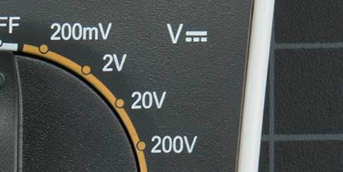
- Set your multimeter to read the appropriate DC voltage. The setting on your multimeter usually indicates the maximum voltage readout it will give. Your stepper drivers shouldn’t read out more than approximately 2 Volts, so set your multimeter appropriate for that.
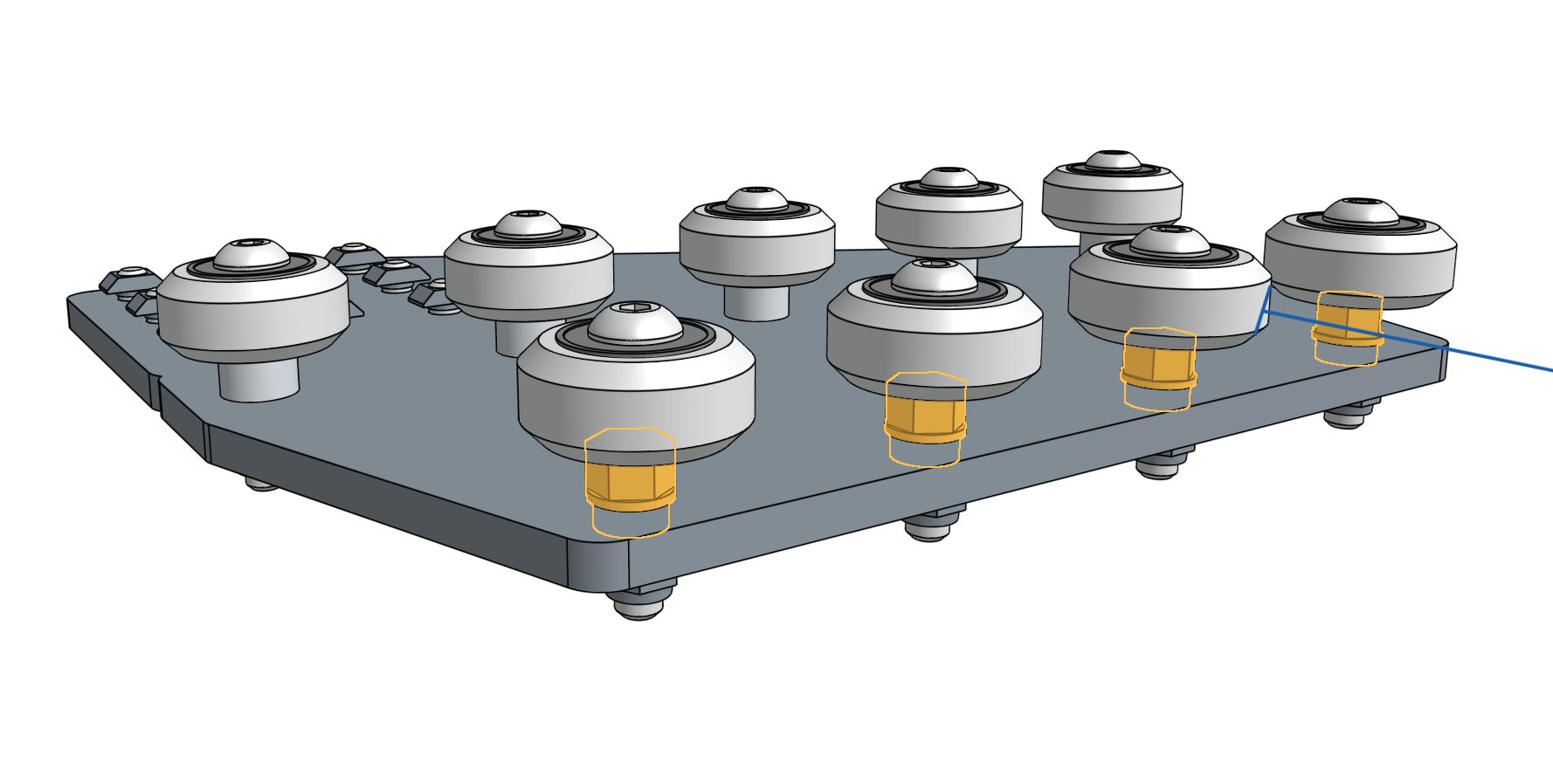
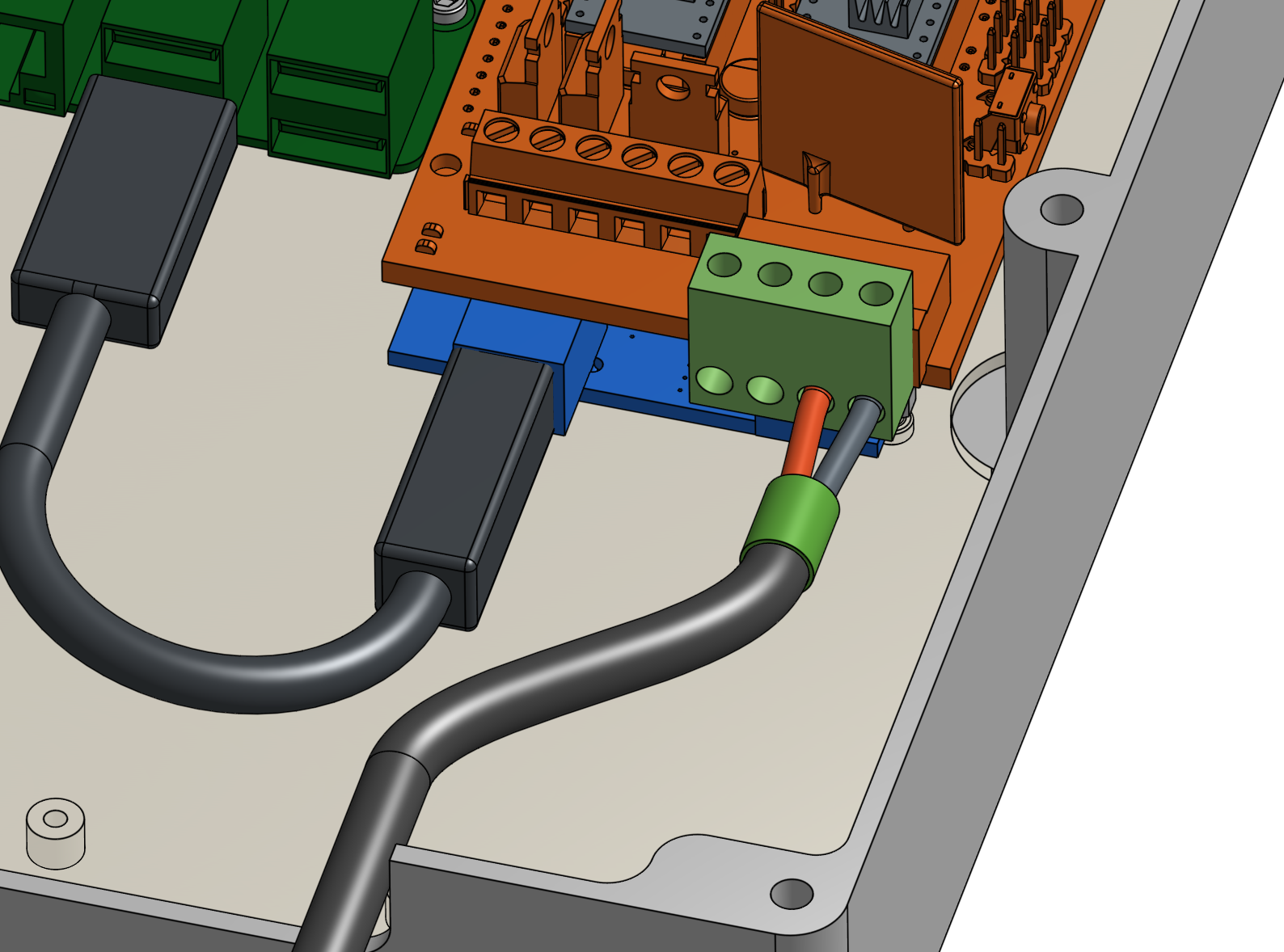
- Put the black reading pin of your multimeter on the screw of the negative RAMPS power cable. If you wired it up as instructed in the FarmBot assembly manual, this should be the far-right screw, holding the black wire. This wire should be connected to the negative output on your power supply.
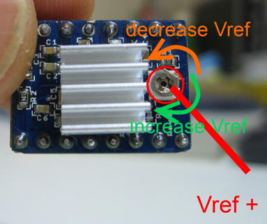
- Put the red reading pin of your multimeter on the stepper driver’s adjust screw.
- Depending on your motors’ requirements, you may increase or decrease the current on the stepper drivers using that same screw you used to read the current.
[quote="Loveny, post:23, topic:1815]
Itrip = Vref / (8xRs)
Rs is 0.1R, so with Vref at 0.6V, Itrip is 0.75A. This is reduced to 0.525A by the A4988 chip for full step operation. The motors are rated at 1.7A, which equates to a Vref of 1.36V (actually 1.9V when you allow for the full step current compensation by the A4988). So you have plenty of room to increase the Vref.[/quote]